
A polysilicon reduction furnace in which the tail gas outlet is connected to an inner extension pipe and its connection method

A reduction furnace and polysilicon technology, applied in chemical instruments and methods, silicon compounds, inorganic chemistry, etc., can solve problems such as the dead zone of reflow in the reduction furnace, slow growth rate at the lower part of the silicon core, and high gas velocity at the inlet of the reduction furnace. Concentration and temperature gradient, solving the problem of silicon core thickness, the effect of stable and safe production

Active Publication Date: 2016-01-13
TIANJIN UNIV
View PDF3 Cites 0 Cited by
  • Summary
  • Abstract
  • Description
  • Claims
  • Application Information

AI Technical Summary

Problems solved by technology

[0005] First, it is easy to cause part of the feed mixed gas to be short-circuited and directly discharged from the exhaust gas outlet with low pressure, which reduces the conversion rate of polysilicon
[0006] Second, due to the high speed and low temperature of the feed gas at the gas inlet, a concentration gradient and a temperature gradient must be generated in the vertical direction of the reduction furnace, resulting in a low deposition reaction rate of polysilicon at the root of the electrode, and at the same time Since the upward flow of gas also tends to drive the polysilicon on the surface of the electrode to move upwards, the combined effect of the two makes the growth rate of the lower part of the silicon core slower, resulting in a thicker upper part of the silicon core and a thinner root, which is not conducive to the safe and stable production of polysilicon.
[0007] Third, this structure leads to high gas velocity at the inlet of the reduction furnace, while the gas velocity at the top of the reduction furnace is low, resulting in a backflow dead zone at the top of the reduction furnace, which reduces the output of polysilicon

Method used


Image

  • A polysilicon reduction furnace in which the tail gas outlet is connected to an inner extension pipe and its connection method
  • A polysilicon reduction furnace in which the tail gas outlet is connected to an inner extension pipe and its connection method
  • A polysilicon reduction furnace in which the tail gas outlet is connected to an inner extension pipe and its connection method

Examples


Embodiment 1

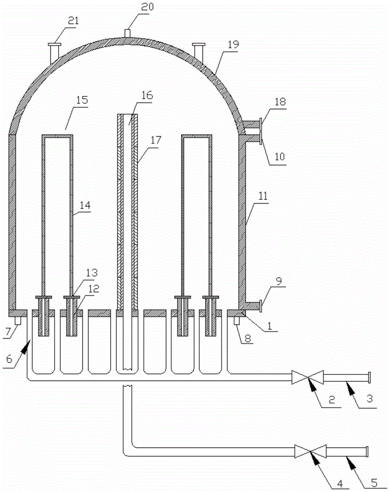
[0029] Example 1: Operation flow 1 of the new polysilicon reduction furnace (taking 15 pairs of rod polysilicon reduction furnaces as an example):

[0030] (1) Open the chassis mixed gas intake control valve 2 and the chassis exhaust gas outlet control valve 4;

[0031] (2) Cooling water is introduced into the furnace body of the reduction furnace, the bottom plate of the reduction furnace, and the top plate of the reduction furnace at the same time;

[0032] (3) The purified SiHCl 3 with H 2 Mix according to a certain ratio, and then spray into the reduction furnace from the mixed gas inlet pipe 3 through the chassis mixed gas inlet control valve 2 and the chassis inlet 6;

[0033] (4) Start the power supply system of the reduction furnace to heat the silicon core, and keep the temperature of the silicon core at 1150°C, and the pressure in the reduction furnace is 0.8Mpa;

[0034] (5) When the temperature of the silicon core surface reaches SiHCl 3 with H 2 Under the con...

Embodiment 2

[0037] Example 2: Operation process 2 of the new polysilicon reduction furnace (taking 15 pairs of rod polysilicon reduction furnaces as an example):

[0038] (1) Open the chassis mixed gas intake control valve 2 and the chassis exhaust gas outlet control valve 4;

[0039] (2) Cooling water is introduced into the furnace body of the reduction furnace, the bottom plate of the reduction furnace, and the top plate of the reduction furnace at the same time;

[0040] (3) The purified SiHCl 3 with H2 Mix according to a certain ratio, and then spray into the reduction furnace from the mixed gas inlet pipe 3 through the chassis mixed gas inlet control valve 2 and the chassis inlet 6;

[0041] (4) Start the power supply system of the reduction furnace to heat the silicon core, and keep the temperature of the silicon core at 1150°C, and the pressure in the reduction furnace is 0.8Mpa;

[0042] (5) When the temperature of the silicon core surface reaches SiHCl 3 with H 2 Under the co...


PUM


Abstract

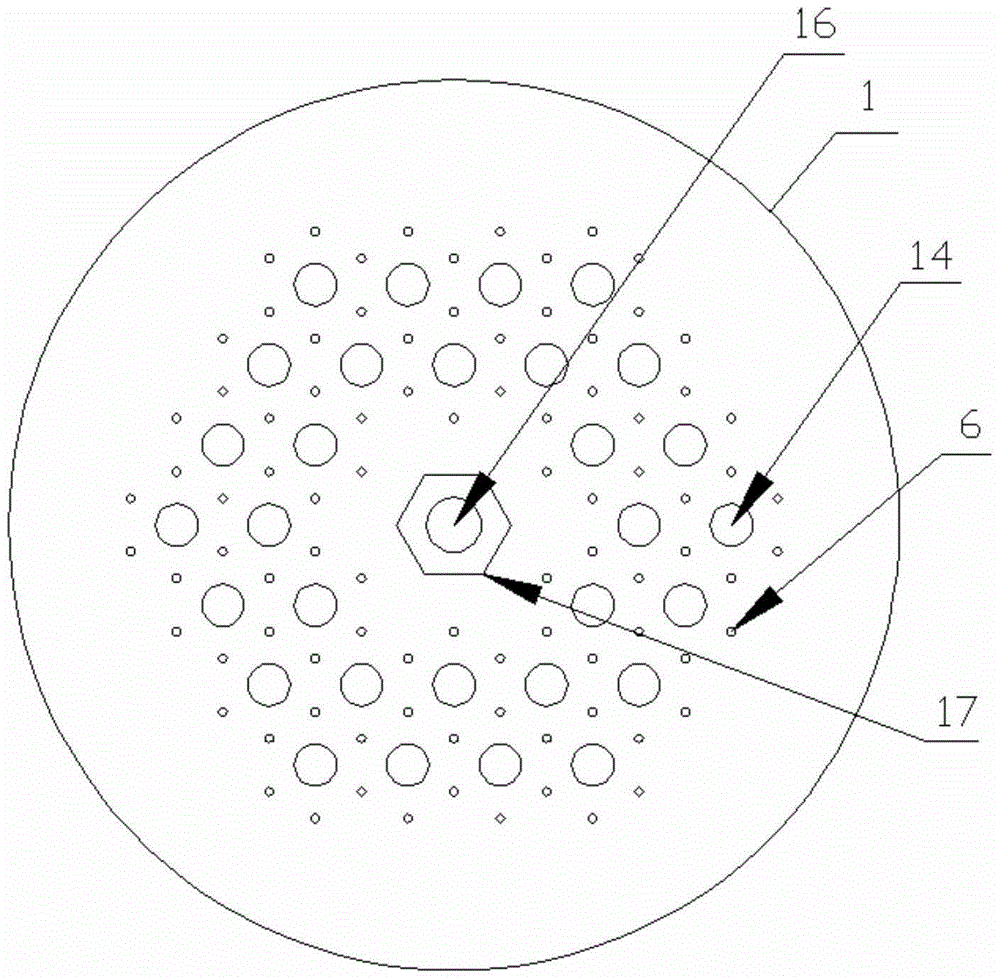
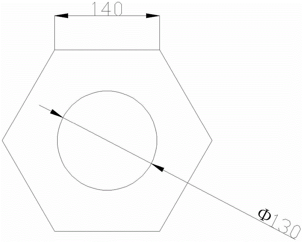
The invention relates to a polycrystalline silicon reduction furnace with an exhaust outlet connected with an inner stretching tube and a connecting method. The top tray of the reduction furnace is an imporous semi-sphere, the exhaust outlet at the center is connected with the inner stretching tube and vertically stretches into the furnace, the inner stretching tube is higher than a silicon rod, a regular hexagon silicon block sheathes outside the inner stretching tube, a layer of electrodes are distributed on the bottom tray of the reduction furnace in regular hexagon, the inner diameter of the regular hexagon silicon block is slightly greater than the outer diameter of the inner stretching tube, so that the regular hexagon silicon block sheathes onto the inner stretching tube conveniently, and the side length of the regular hexagon is 1.05-1.2 times of the outer diameter of the inner stretching tube. The inner stretching tube connected with the exhaust outlet prevents mixed gas in the furnace from going into a short line, thus prolonging the staying time of the mixed gas in the reduction furnace so as to improve the conversion rate of the mixed gas; the inner stretching tube forces the mixed gas to pass through the upper space of the furnace, thus effectively avoiding generating a backflow dead area at the top of the reduction furnace; the regular hexagon nut-shaped silicon block sheathed outside the inner stretching tube also can play a role in depositing polycrystalline silicon, and has a positive role in increasing the yield of polycrystalline silicon.

Description

technical field [0001] The invention belongs to the technical field of polysilicon production, in particular to an energy-saving large-scale polysilicon reduction furnace for producing polysilicon by the Siemens method; it relates to a specific structure and connection method of a novel polysilicon reduction furnace with an exhaust gas outlet connected to an inner extension pipe. Background technique [0002] At present, polysilicon production enterprises at home and abroad mainly adopt the "improved Siemens method". The production process of this method is to synthesize trichlorosilane with hydrogen chloride and silicon powder at a certain temperature, then rectify and purify the trichlorosilane, and mix the purified high-purity trichlorosilane with hydrogen in a certain proportion It enters the polysilicon reduction furnace under temperature and pressure, and performs vapor deposition reaction on the energized high-temperature silicon core to generate polysilicon. The unre...

Claims


Application Information

Patent Timeline
Patent Type & Authority Patents(China)
IPC IPC(8): C01B33/035
Inventor 刘春江耿洋黄哲庆袁希钢
Owner TIANJIN UNIV
Learn More