Nano-porous material energy absorption structure packaged by high polymer materials

A polymer material and nano-porous technology, applied in the field of energy-absorbing structures, can solve problems such as non-reusable use, inability of materials to resist impact, permanent buckling of holes, etc., and achieve the effect of low material cost, light weight, and simple structural design

Active Publication Date: 2014-06-25
SHAANXI COAL & CHEM TECH INST
View PDF4 Cites 10 Cited by
  • Summary
  • Abstract
  • Description
  • Claims
  • Application Information

AI Technical Summary

Problems solved by technology

Then under impact loads, the pores permanently buckle, after which the material cannot resist new impacts, rendering it unusable

Method used


Image

  • Nano-porous material energy absorption structure packaged by high polymer materials
  • Nano-porous material energy absorption structure packaged by high polymer materials
  • Nano-porous material energy absorption structure packaged by high polymer materials

Examples


Embodiment 1

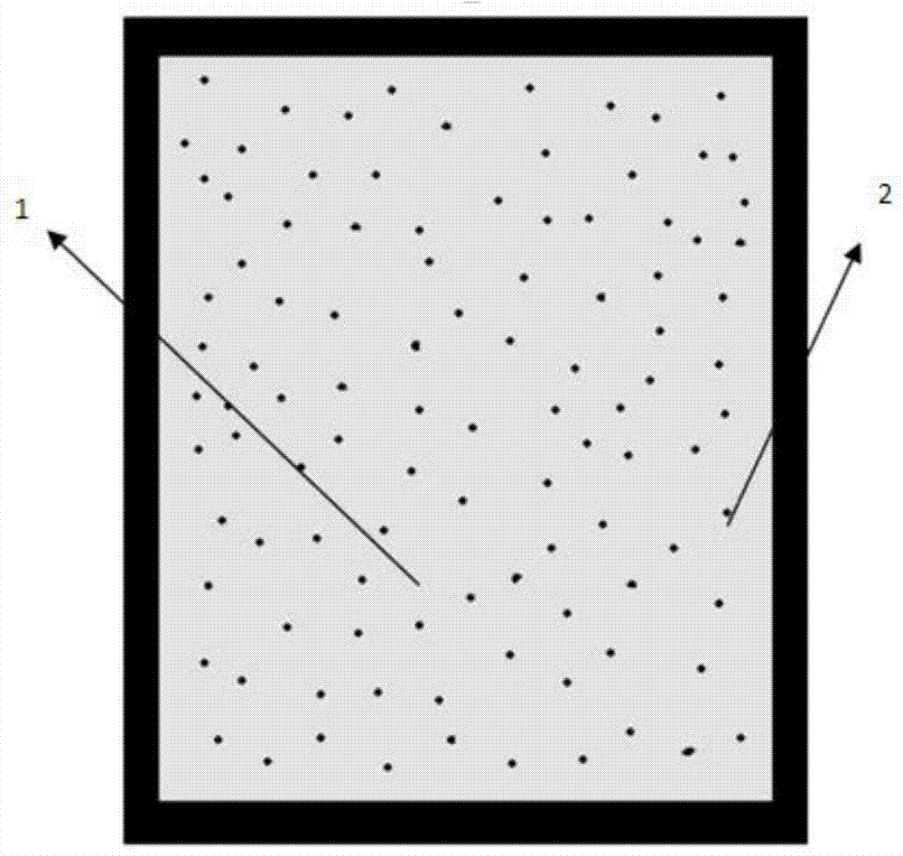
[0047] Such as figure 2 As shown, in this embodiment, a nanoporous material energy-absorbing structure encapsulated by a polymer material is used. The nanoporous material is ZSM-5 zeolite, and its average pore diameter is 0.5 nm. After mixing it with water, it is configured to have a concentration of 1 :1 solution, the polymer material shell 2 made of polyvinyl chloride is used to encapsulate the nanoporous material mixed solution 1, then the solid-liquid interfacial tension of the nanoporous material energy-absorbing structure can be used as a constant, and at this time, the solid-liquid interfacial tension The contact angle of the liquid interface mainly depends on the hydrophobicity of the channel. In the case of the same infiltration volume, ZSM-5 zeolite material has strong hydrophobicity, large contact angle, strong infiltration pressure, and large surface energy, and vice versa.

[0048] At the same time, at the nanometer scale, the fluid cannot be analyzed as a conti...

Embodiment 2

[0055] Such as figure 2 As shown, this embodiment is based on the energy-absorbing structure of nanoporous materials nested and packaged with metal and polymer materials. The nanoporous material is porous silica with an average pore diameter of 5 nm. It is mixed with sodium chloride solution and configured as For a solution with a concentration of 1:2, the nanoporous material mixture 1 is encapsulated by a polymer material shell 2 made of styrene-butadiene rubber.

Embodiment 3

[0057] Such as figure 2 As shown, this embodiment is based on the energy-absorbing structure of nanoporous materials nested and packaged with metal and polymer materials. The nanoporous material is carbon nanotubes with an average pore diameter of 40 nm. After mixing it with mercury, it is configured to have a concentration of 1 :5 solution, using the polymer material shell 2 made of natural rubber to encapsulate the nanoporous material mixture 1.


PUM

PropertyMeasurementUnit
pore sizeaaaaaaaaaa
pore sizeaaaaaaaaaa
pore sizeaaaaaaaaaa

Abstract

A nano-porous material energy absorption structure packaged by high polymer materials comprises one-layer or multi-layer polymer material outer shell and nano-porous material mixed liquid packaged in the polymer material outer shell. The nano-porous material mixed liquid is formed by the fact that nano-porous materials and non-infiltrating liquid are mixed, and the maximum mass ratio of the nano-porous materials and the non-infiltrating liquid is 3:1. The nano-porous material is zeolite or porous silicon earth or nano-porous metal or nano-porous metal oxides or a carbon nano tube or activated carbon or nano-porous polymer materials. The non-infiltrating liquid is water or an inorganic salt solution or an organic solution or an oil-based solution or liquid metal or a rubber matrix. The polymer material outer shell is made of rubber or polyethylene or chloroethylene. According to the nano-porous material energy absorption structure packaged by the high polymer materials, energy is converted into solid-liquid two-phase surface tension, friction force and deformation energy of the polymer materials, so that energy absorption is effectively improved, the structure is simple, meanwhile, the weight is relatively low, and mass production and application are facilitated.

Description

technical field [0001] The invention relates to an energy-absorbing structure, in particular to a nano-porous material energy-absorbing structure encapsulated by a polymer material. Background technique [0002] So far, most energy-absorbing materials are "soft materials", including fiber-reinforced polymers, honeycomb metal (aluminum) / foam materials, etc. When these materials are subjected to external loads, they absorb the energy and stress waves brought about by the impact through the principle of "multi-point action" (large deformation, buckling, spallation, fracture, friction, etc.), thereby protecting the target structure. These materials can achieve better energy-absorbing effects when subjected to linear and low-speed impacts, but once subjected to nonlinear, high-speed impacts or even multiple impacts, their energy-absorbing effects will be greatly reduced, mainly due to stress regionalization and material The response time is too long. [0003] With the deepening...

Claims


Application Information

Patent Timeline
Patent Type & Authority Applications(China)
IPC IPC(8): F16F7/12
Inventor 陈曦
Owner SHAANXI COAL & CHEM TECH INST
Why Eureka
Try Eureka