Exposure apparatus and focusing and leveling method thereof

A focus, leveling, and spot technology, applied in the field of photolithography, can solve problems such as falling outside the silicon wafer, invalid spot, and large amount of calculation for spot validity judgment, so as to improve time performance, improve measurement accuracy, and reduce effectiveness The effect of judging and switching time

Active Publication Date: 2014-06-25
SHANGHAI MICRO ELECTRONICS EQUIP (GRP) CO LTD
View PDF7 Cites 9 Cited by
  • Summary
  • Abstract
  • Description
  • Claims
  • Application Information

AI Technical Summary

Problems solved by technology

In these technologies, a set of optical systems is usually used to generate multiple light spots covering the entire exposure field for measurement. In the fringe field position, some measurement light spots may fall outside the silicon wafer and cause the light spots to be invalid. At this time, the current position needs to be calculated. The effectiveness of the spot array, using the measurement value of the still valid spot for focus and leveling

Method used


Image

  • Exposure apparatus and focusing and leveling method thereof
  • Exposure apparatus and focusing and leveling method thereof
  • Exposure apparatus and focusing and leveling method thereof

Examples


Embodiment Construction

[0024] Specific embodiments of the present invention will be described in detail below in conjunction with the accompanying drawings.

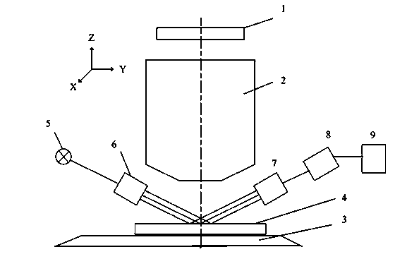
[0025] figure 1 Shown is a schematic structural view of the scanning exposure equipment used in the present invention, the scanning exposure equipment has a mask 1, a projection objective lens 2, a workpiece table 3, a silicon wafer 4, a light source 5, a projection unit 6, a detection unit 7, and a signal processing unit 8 , main controller 9 . The projection objective lens 2 is used to project the pattern of the mask 1 onto the upper surface of the silicon wafer 4 located on the workpiece table 3, the light emitted by the light source 5 is incident on the silicon wafer 4 through the projection unit 6, and is reflected by the upper surface of the silicon wafer 4 Afterwards, it is received by the detection unit 7, and after photoelectric conversion and signal processing are performed on the received optical signal by the signal processing uni...


PUM


Abstract

A projection exposure apparatus comprises a mask, a projection lens, a workpiece stage, a silicon wafer, a light source, a projection unit, a detection unit, a signal processing unit and a main controller; the projection lens is used to project the pattern of a mask to the upper surface of the silicon wafer on the workpiece stage; light emitted by the light source is incident on the silicon wafer via the projection unit, is reflected by the upper surface of the silicon wafer, and is received by the detection unit; and the signal processing unit processes the received light signal, obtains the pose information of the silicon wafer upper surface in a current measurement area, and sends the information to the main controller. Multiple measurement light spots are arranged on the silicon wafer of the projection exposure apparatus, multiple measurement points are arranged at the external of an exposure field, and multiple measurement light spots are arranged around the external of the exposure field.

Description

technical field [0001] The invention relates to the field of photolithography, in particular to a scanning exposure device and a focusing and leveling measurement method in a projection photolithography machine. Background technique [0002] A projection lithography machine is a device that projects the pattern on the mask onto the upper surface of the silicon wafer through the objective lens. In the projection exposure equipment, there must be an automatic focus control system to accurately bring the silicon wafer to the designated exposure position, and there are many different technical solutions for realizing this system. At present, non-contact photoelectric measurement technology is commonly used, among which the focusing technology of NIKON, CANON and other companies is the most representative. In these technologies, a set of optical systems is usually used to generate multiple light spots covering the entire exposure field for measurement. In the fringe field positi...

Claims


Application Information

Patent Timeline
IPC IPC(8): G03F7/20
Inventor 李志丹程雪陈飞彪
Owner SHANGHAI MICRO ELECTRONICS EQUIP (GRP) CO LTD
Why Eureka
Try Eureka