A single-cell capturing chip

A single-cell and chip technology, applied in the field of microfluidics, can solve the problems of incomplete replacement of internal and external liquid, limited amount of new liquid, and reduced effect, and achieve the effect of simple and fast discrimination, low probability, and prevention of cell escape

Active Publication Date: 2016-03-30
SUZHOU INST OF NANO TECH & NANO BIONICS CHINESE ACEDEMY OF SCI
View PDF3 Cites 8 Cited by
  • Summary
  • Abstract
  • Description
  • Claims
  • Application Information

AI Technical Summary

Problems solved by technology

Moreover, the amount of new liquid that is diffused into by concentration difference is very limited, and the replacement of internal and external liquids is not complete. When the diameter of the central isolation culture area increases, the effect of liquid replacement by diffusion will decrease.

Method used


Image

  • A single-cell capturing chip
  • A single-cell capturing chip
  • A single-cell capturing chip

Examples


Embodiment 1

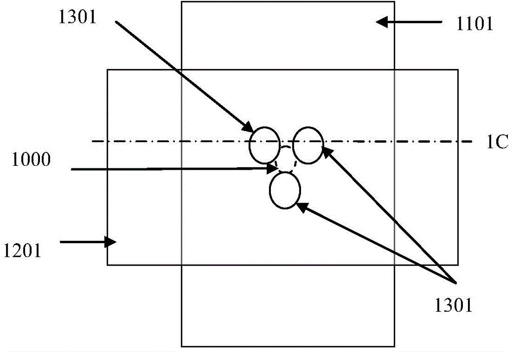
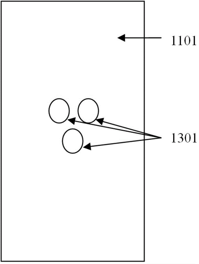
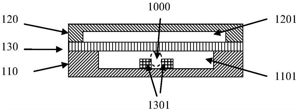
[0073] Example 1 Figure 1~3It is a schematic diagram of the single cell capture chip of Example 1 of the present invention, and the chip is mainly composed of three structural layers stacked one above the other. The bottom layer is the fluid flow layer 110, the upper layer is the pneumatic control layer 120, and there is an elastic membrane 130 between the two layers. There is a liquid flow channel 1101 in the liquid flow layer 110, with a width of 100 microns and a height of 20 microns. There are interfaces at both ends to communicate with the outside of the chip. There are three protruding micropillars 1301 at the bottom of the local area of ​​the liquid flow channel 1101, with a diameter of 10 microns and a height of 20 microns. 10 microns, the area surrounded by the micro-pillars is the single cell capture area 1000. In the pneumatic control layer 120 there is a first pneumatic control channel 1201 with a width of 100 micrometers, passing through the liquid flow channe...

Embodiment 2

[0077] Example 2 Figure 4 , 5 It is a schematic structural diagram of the single cell capture chip in Example 2 of the present invention, and the chip is mainly composed of three structural layers stacked one above the other. The bottom layer is the fluid flow layer 110, the upper layer is the pneumatic control layer 120, and there is an elastic membrane 130 between the two layers. There is a liquid flow channel 1101 in the liquid flow layer 110, with a width of 100 microns and a height of 20 microns. There are interfaces at both ends to communicate with the outside of the chip. Three protruding micropillars 1401 protrude from the local area of ​​the elastic membrane 130 toward the direction of the liquid flow channel. The diameter is 10 microns, the height is 10 microns, and the area surrounded by the micro-pillars is the single cell capture area 1000. In the pneumatic control layer 120 , there is a first pneumatic control channel 1201 passing over the single cell captur...

Embodiment 3

[0080] Example 3 Figure 6 , 7 It is a schematic diagram of the structure of the single cell capture chip in Example 3 of the present invention, and the chip is mainly composed of three structural layers stacked one above the other. The bottom layer is the fluid flow layer 110, the upper layer is the pneumatic control layer 120, and there is an elastic membrane 130 between the two layers. There is a liquid flow channel 1101 in the liquid flow layer 110, with a width of 100 microns and a height of 20 microns. There are interfaces at both ends to communicate with the outside of the chip. There are three protruding micropillars 1301 at the bottom of the local area of ​​the liquid flow channel 1101, with a diameter of 10 microns and a height of 20 microns. 10 microns, the area surrounded by the micro-pillars is the single cell capture area 1000. There is a first pneumatic control pipeline 1201 in the pneumatic control layer 120 , wherein the first pneumatic control pipeline 12...


PUM


Abstract

A single-cell capturing chip is disclosed. The chip comprises a liquid layer, an elastic membrane layer and a driving mechanism, wherein the liquid layer comprises a liquid path, the liquid path is communicated with outside of the chip through a port of a liquid feeding pipe and a port of a liquid discharging pipe, the elastic membrane layer comprises an elastic membrane on the liquid path, and the driving mechanism is at least used for driving a local zone of the elastic membrane to generate deformation and/or displacement towards the liquid path, and therefore a cell cavity for entrapping a single cell from liquid flowing through the liquid path is formed between the elastic membrane layer and the liquid layer. By presetting the cell cavity, the chip increases the single-cell capturing efficiency and reduces the number of fed cells needed for capturing.

Description

technical field [0001] The invention belongs to the field of microfluidic technology, in particular to a single cell capture chip. Background technique [0002] With the continuous development of biotechnology research methods, the research level of biology is deepening and expanding from cell population to single cell level. Each cell is unique in time and space. Although they may come from the same ancestor, different time and space environments determine their specific genetic expression, resulting in different biological traits, which have great impact on evolution, drug resistance, and gene expression. Such research is of great value. However, analysis methods based on cell populations often conceal the differences between different cells within the population, ignoring these small but important information. Therefore, there is an urgent need to develop single-cell-based culture and analysis methods to study the differences between individual cells and understand the ...

Claims


Application Information

Patent Timeline
Patent Type & Authority Applications(China)
IPC IPC(8): C12M1/00
Inventor 甘明哲陈立桅
Owner SUZHOU INST OF NANO TECH & NANO BIONICS CHINESE ACEDEMY OF SCI
Why Eureka
Try Eureka