Wing antenna integrating structures and functions
A wing antenna and wing technology, applied in the field of aircraft antennas, can solve problems such as wing structure vibration and deformation, unspecified antenna layout, radio frequency signal connection methods and manufacturing methods, and reduce antenna temperature, so as to reduce antenna performance Reduce or fail, ensure the stability of electromagnetic performance, and improve the effect of aerodynamic performance
- Summary
- Abstract
- Description
- Claims
- Application Information
AI Technical Summary
Problems solved by technology
Method used
Image

Examples
Embodiment Construction
[0047] The present invention will be specifically introduced below in conjunction with the accompanying drawings and specific embodiments.
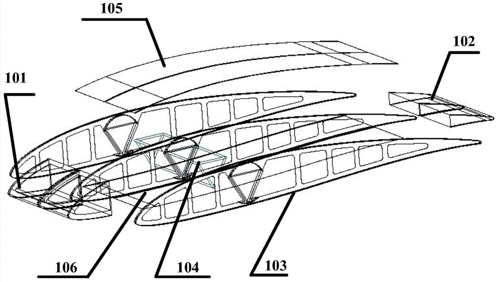
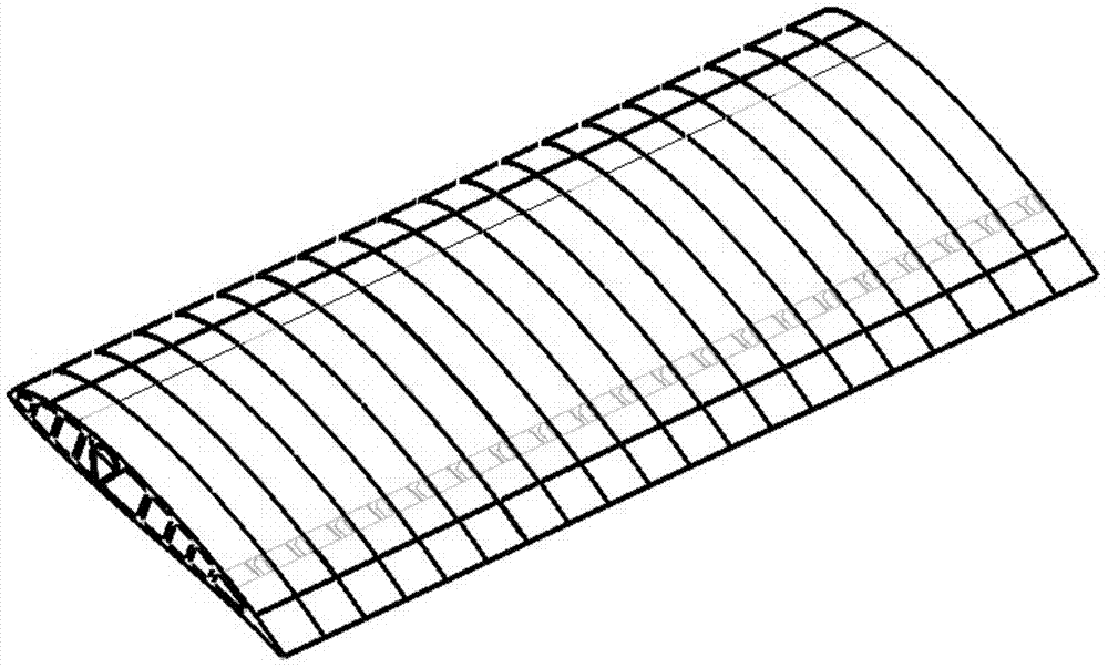
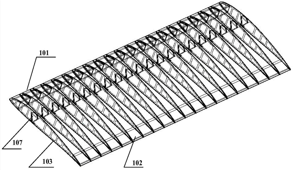
[0048] refer to figure 1 , figure 2 with image 3 , the structure-function integrated wing antenna of the present invention includes: a wing frame, a wing skin, and a control and signal processing system 107 . The wing skin covers the outside of the wing skeleton, and the wing skin is divided into an upper skin 105 and a lower skin 106 according to the positions covering the wing skeleton, both of which have identical structures. The structure of the wing skeleton, the wing skin, and the control and signal processing system 107 will be introduced respectively below.
[0049] refer to figure 1 , figure 2 with image 3 , the wing frame includes: ribs 103 , spars 104 , wing leading edge 101 and wing trailing edge 102 . There are several ribs 103 arranged in parallel; the spar 104 is triangular in shape and is a hollow structure, whi...
PUM
 Abstract
Description
Claims
Application Information