Powder injection lance and method of refining molten iron using the powder injection lance

A technology for molten iron and spray guns, which is applied to the improvement of process efficiency, furnaces, manufacturing converters, etc., can solve problems such as increased manufacturing costs, prolonged refining time, and inability to blow powder, and achieve the effect of improving heating efficiency.

Active Publication Date: 2014-06-25
JFE STEEL CORP
View PDF11 Cites 11 Cited by
  • Summary
  • Abstract
  • Description
  • Claims
  • Application Information

AI Technical Summary

Problems solved by technology

In Patent Document 1, although the temperature of molten iron is raised by adding a carbon source to the generated slag, the sulfur contained in the carbon source is mixed in, resulting in an increase in the sulfur concentration in the steel.
In addition, there is a problem that the refining time is prolonged in order to secure the burning time of the carbon source, resulting in an increase in manufacturing cost
In addition, there is also a problem that CO is naturally generated by burning carbon sources. 2 increased production of
[0022] Furthermore, in the methods disclosed in Patent Documents 4, 5, and 6, a top blowing lance consisting of a 4-layer tube or 5-layer tube structure is used, and the dephosphorization agent etc. etc. Reactive powder insufflation
In addition, the amount of injection and the flow rate of propane are low, so it cannot be expected to have a sufficient effect on reducing the ratio of molten iron

Method used


Image

  • Powder injection lance and method of refining molten iron using the powder injection lance
  • Powder injection lance and method of refining molten iron using the powder injection lance
  • Powder injection lance and method of refining molten iron using the powder injection lance

Examples


Embodiment approach 1)

[0095] Hereinafter, the present invention will be described in more detail with reference to the drawings.

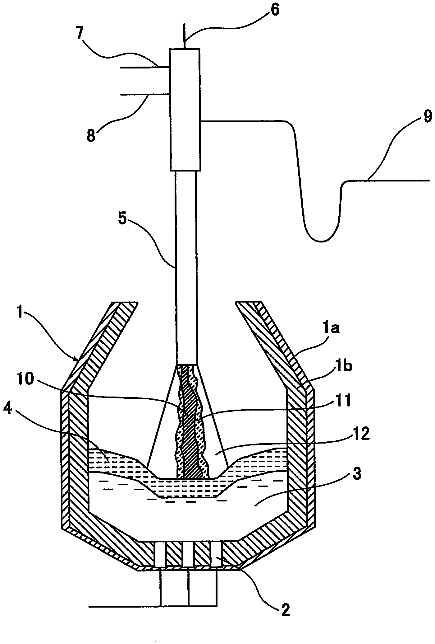
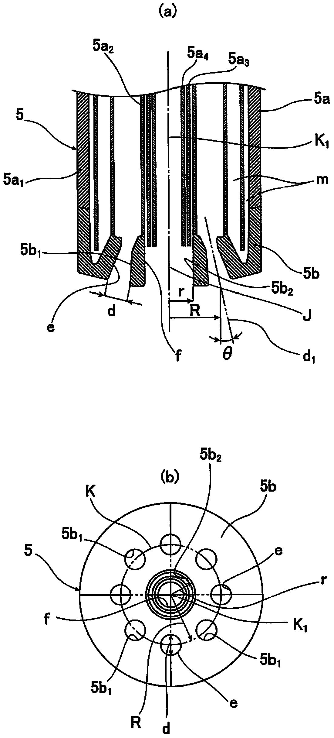
[0096] figure 1 It is a figure which shows the state which installed the powder injection lance based on this invention in the converter type refinery facility, figure 2 (a), figure 2 (b) is an enlarged view showing the cross section of the front end portion of the powder injection gun according to the present invention. Furthermore, in Embodiment 1 of the present invention, the reaction container includes, for example, an iron bath type refining furnace.

[0097] Reference numeral 1 in the figure denotes a furnace body. The furnace body 1 is configured to include an iron shell 1a forming the skeleton of the furnace body 1, and a refractory layer 1b applied inside the iron shell 1a.

[0098] In addition, reference numeral 2 denotes a bottom tuyere, which is installed at the bottom of the furnace body 1, and is used to blow in an inert gas such as Ar gas to stir th...

Embodiment 1

[0124] As a top-blown lance, use the above-mentioned figure 2 For the spray gun with the structure shown, the liquid iron with the composition shown in Table 2 is filled together with iron scrap into the above-mentioned 2.5t capacity figure 1 The combined top-bottom blowing converter shown in Table 3 carried out dephosphorization blowing under the conditions.

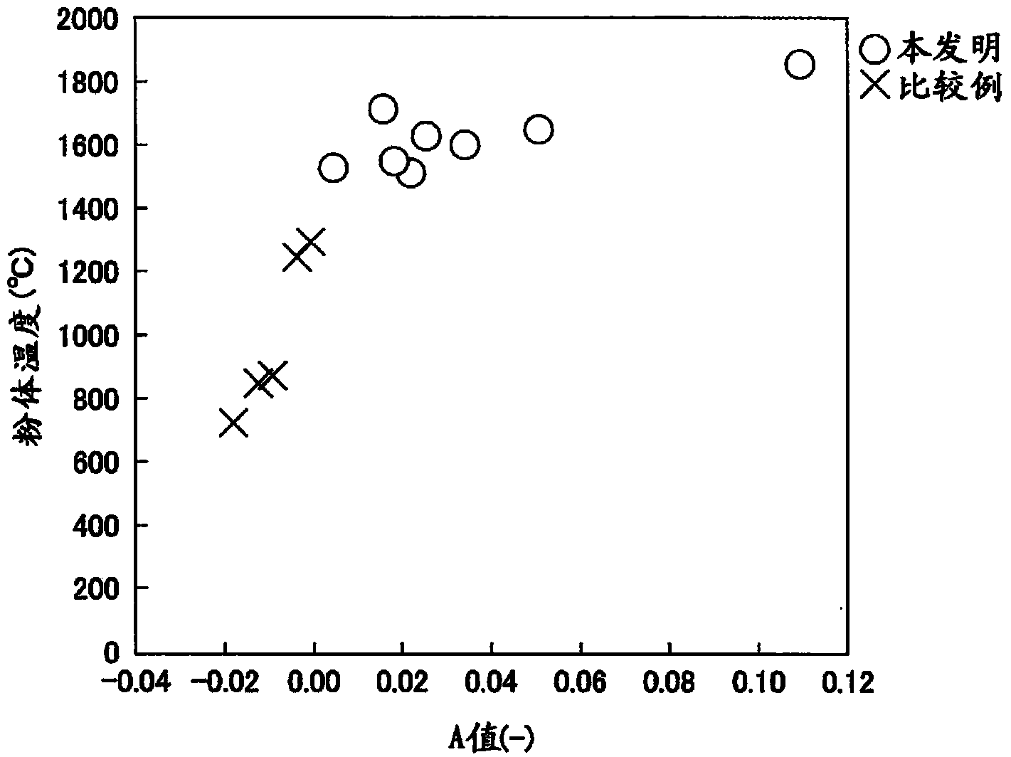
[0125] And thereafter, liquid discharge and slagging are carried out, and then the molten iron after the dephosphorization treatment is filled into the same top-bottom re-blowing converter together with the iron scrap, and decarburization blowing is carried out under the conditions of Table 3, thereby targeting at The effect of the A value of the top blowing lance on the mixing ratio of molten iron was investigated. Table 4 shows the results thereof.

[0126] In addition, during the dephosphorization blowing process, after filling the furnace with iron scrap, it is filled with molten iron at a temperature of 1350°C, ...

Embodiment approach 2)

[0146] Embodiment 2 of the present invention is directed to an oxidation refining process in which an oxidizing gas for refining is supplied from a top blowing lance to molten iron accommodated in a converter. As the oxidation refining treatment, preliminary dephosphorization treatment of molten iron and decarburization refining treatment of molten iron are currently performed, and the present invention can be applied to any of the oxidation refining treatment. When the present invention is applied to decarburization and refining of molten iron, the present invention can be implemented on molten iron after preliminary dephosphorization treatment, or can be implemented on molten iron that has not been subjected to preliminary dephosphorization treatment. The present invention can also be applied when the present invention is applied to the preliminary dephosphorization treatment and the molten iron refined by the preliminary dephosphorization treatment is decarburized and refine...


PUM


Abstract

A powder injection lance is provided with: a refining oxygen gas injection nozzle which has multiple ejection openings that are arranged at intervals along a circular trajectory and inject an oxygen gas into an iron bath housed in a reaction vessel; and a burner nozzle which has an axial center coaxial with the central axis of the circular trajectory, and which has an ejection opening which forms a flame on the inside of the refining oxygen gas injection nozzle and which injects into the iron bath a powder to which heat has been transferred by the flame. An indicator showing the positional relation between the ejection opening of the refining oxygen gas injection nozzle and the ejection opening of the burner nozzle fulfills A=1.7(R-r-d/2)/L+tan(theta-12 DEG )-0.0524>0. Here, R is the radius (mm) of the circular trajectory, r is the radius (mm) of the ejection opening of the burner nozzle, d is the diameter (mm) of the ejection openings of the refining oxygen nozzle, theta is the inclination angle (DEG) of the axial center of the refining oxygen gas injection nozzle, and L is the lance height (mm). By this means, the efficiency of heat transfer to the iron bath is improved.

Description

technical field [0001] The present invention relates to a powder injection lance with a spray burning function, and a refining method and a smelting reduction method of molten iron using the powder injection lance. Background technique [0002] From the viewpoint of environmental protection, it is imperative to suppress CO in the steel manufacturing process. 2 emissions. In order to reduce CO 2 In terms of emissions, in the steelmaking process, measures such as increasing the use of cold iron sources such as scrap iron as iron sources and reducing the blending ratio of molten iron have been studied and implemented. The reason for increasing the use of cold iron sources is as follows: When producing steel products, a large amount of energy is required to reduce and melt iron ore in the process of producing molten iron (molten iron) in a blast furnace, and at the same time, also emit large amounts of CO 2 , in contrast, the cold iron source only needs the heat of fusion, s...

Claims


Application Information

Patent Timeline
Patent Type & Authority Applications(China)
IPC IPC(8): C21C5/46C21C1/02C21C5/30
CPCC21C5/35C21C5/462C21C5/32C21C1/02C21C5/4606C21C5/5217F27D2019/0034F27D2019/0075Y02P10/20C21C7/0037
Inventor 奥山悟郎菊池直树内田祐一高桥幸雄佐藤新吾中濑宪治田惠太三木祐司
Owner JFE STEEL CORP
Why Eureka
Try Eureka