Novel drilling method for shaft drilling machine

一种钻井法、竖井的技术,应用在辅助类竖井建设,建设施工用竖井,矿产开采领域,能够解决加压力和扭矩限制、钻进效率低、很难快速成井施工等问题,达到提高加压力、提高掘进效率、缩短建井周期的效果

Active Publication Date: 2014-07-02
CHINA RAILWAY ENGINEERING EQUIPMENT GROUP CO LTD
View PDF6 Cites 36 Cited by
  • Summary
  • Abstract
  • Description
  • Claims
  • Application Information

AI Technical Summary

Problems solved by technology

[0002] At present, the drilling method uses large vertical well drilling rigs for construction, and the degree of mechanization is high. However, due to the use of decompression drilling and gravity guidance, the pressure and torque are greatly limited, so the drilling efficiency is low, and it is difficult to achieve rapid well construction.

Method used


Image

  • Novel drilling method for shaft drilling machine
  • Novel drilling method for shaft drilling machine
  • Novel drilling method for shaft drilling machine

Examples


Embodiment 1

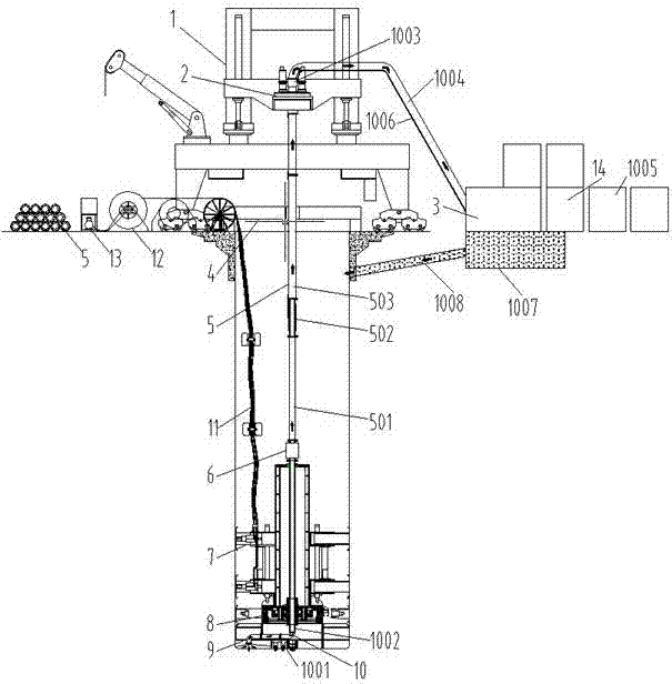
[0019] Embodiment 1: as figure 1 As shown, a new type of drilling method shaft drilling rig, including derrick 1, main drive 2, mud treatment station 3, sealing flat car 4, drill pipe 5, flexible connector 6, stable pressure device 7, torque amplification driver 8, knife Pan 9, slag discharge system 10, power pipeline 11, pipeline extension device 12, hydraulic station 13, electrical cabinet 14, etc. Install derrick 1, sealing flat car 4, pipeline extension device 12, hydraulic station 13, electrical cabinet 14, mud treatment station 3, etc. at and near the wellhead, and install main drive 2 and other equipment on derrick 1. The derrick 1 controls the main drive 2 to lift and slide to realize the lifting and drilling of the equipment. The main drive 2 drives the drill pipe 5, and the drill pipe 5 drives the cutter head through the flexible connector 6 and the torque amplification driver 8 to perform shaft drilling. The stabilizing pressurizing device 7 is used to provide driv...

Embodiment 2

[0021] Embodiment 2: as figure 2 As shown, a new type of shaft drilling rig with drilling method mainly includes derrick, main drive, top rotary joint, sealing flat car, drill pipe, flexible connector, stable pressure device, torque amplification driver, cutter head, slag discharge system, power Pipelines, electrical cabinets, hydraulic stations, mud treatment stations, pipe reels. The derrick and the sealing flat car are installed at the wellhead, the main drive is installed on the derrick, the lower part of the main drive is connected to the drill pipe, the drill pipe is provided with a flexible connector, the lower part of the drill pipe is equipped with a stable pressure device, and the lower end of the drill pipe passes through the torque amplification drive Connect to cutter head.

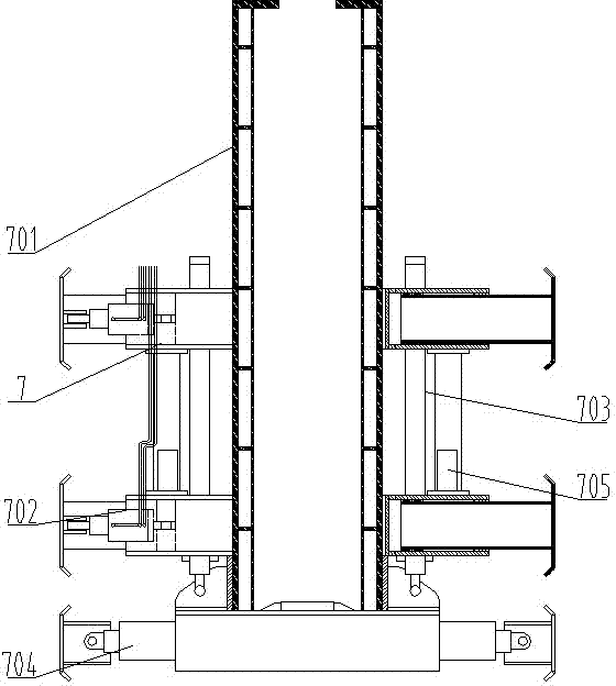
[0022] The stable pressurizing device 7 includes a guide column 701, a stabilizer 702, a propulsion hydraulic cylinder 703, a servo stabilizer 704, a direction sensor 705, and the like. Th...

Embodiment 3

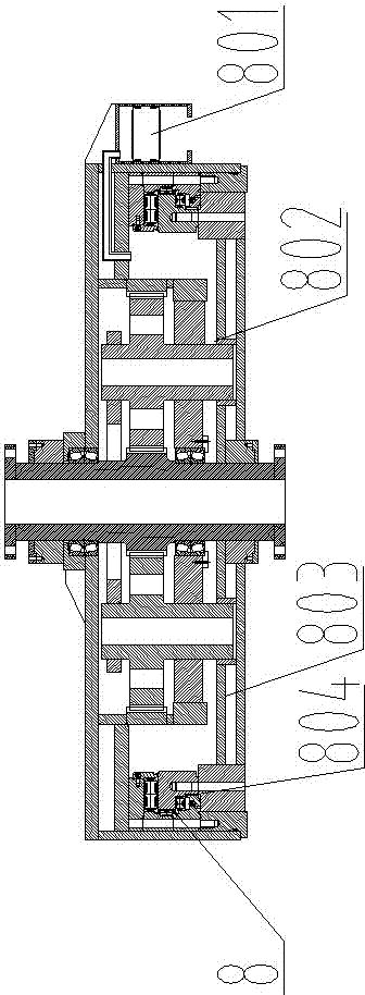
[0024] Embodiment 3: as image 3 As shown, a new type of drilling method shaft drilling rig, the torque amplification driver 8 includes a pressure balance valve 801, a planetary reducer 802, a driving flange 803, a main bearing 804, etc., and the pressure balance valve 801 is installed on the side of the driver. The internal pressure of the driver is communicated with the external pressure to realize the pressure balance inside and outside the driver. The planetary reducer 802 amplifies the torque input by the drill pipe 5 and drives the driving flange 803 with high torque and low drilling speed. The main bearing 804 is installed inside the driver. The drive housing and the drive flange are used to bear the reverse thrust transmitted by the cutter head 9 and other various reaction forces during the excavation process.

[0025] Other structures are with embodiment 1.


PUM


Abstract

A novel drilling method for a shaft drilling machine mainly comprises a derrick and an opening-sealing flat wagon which are arranged at a well opening, and further comprises a drill rod, a flexible connector, a stable pressing device, a torque amplification driving device, a cutter head, a slag discharging system, a mud treatment station, an electric appliance cabinet, a hydraulic pressure station and a power pipeline. A main drive is arranged on the derrick, the lower portion of the main drive is connected with the drill rod, the flexible connector is arranged on the drill rod, the lower end of the drill rod is connected with the torque amplification driving device, the lower end of the torque amplification driving device is connected with the cutter head, the stable pressing device is arranged outside the torque amplification driving device; muck dug by the cutter head in a well is delivered to the mud treatment station on the ground through the slag discharging system. According to the novel drilling method for the shaft drilling machine, stability of the whole machine is increased, pressing force of equipment is improved, drilling torque is increased, construction in soft soil layers is available and construction in rock stratums of high hardness is also available, guide is more accurate, so that shaft construction efficiency can be improved, shaft construction cycle is shortened, and finished well quality is improved.

Description

technical field [0001] The invention belongs to drilling machinery and is mainly used in the fields of mineral mining, construction shafts, auxiliary shaft construction and the like. Background technique [0002] At present, the drilling method uses large-scale vertical drilling rigs for construction, and the degree of mechanization is high. However, due to the use of decompression drilling and gravity guidance, the pressure and torque are greatly limited, so the drilling efficiency is low, and it is difficult to achieve rapid well construction. Contents of the invention [0003] The technical problem to be solved by the present invention is to provide a new type of shaft drilling rig with drilling method, which improves the pressure and torque, and at the same time enables the equipment to have the function of forced guidance, and the well-forming precision is higher. [0004] In order to solve the above technical problems, the following technical solutions are adopted: ...

Claims


Application Information

Patent Timeline
Patent Type & Authority Applications(China)
IPC IPC(8): E21D1/06
CPCE21D1/06E21B3/02E21B4/006E21B4/20E21B15/00
Inventor 赵华李建斌尼古劳斯·K张宁川肖威卓兴建王杜娟贾连辉董艳萍周倩
Owner CHINA RAILWAY ENGINEERING EQUIPMENT GROUP CO LTD
Why Eureka
Try Eureka