Welding type LED substrate and manufacturing technology thereof

A technology of LED substrate and manufacturing process, which is applied in the direction of lighting devices, cooling/heating devices of lighting devices, light sources, etc., can solve the problems of small thermal conductivity of thermal paste, unsatisfactory heat dissipation effect, and failure to achieve joint surface, etc., to achieve production High efficiency, significant social significance and economic benefits, high production efficiency and high yield

Inactive Publication Date: 2014-07-02
ZHEJIANG GEMCORE TECH
View PDF7 Cites 1 Cited by
  • Summary
  • Abstract
  • Description
  • Claims
  • Application Information

AI Technical Summary

Problems solved by technology

However, this technology also has major deficiencies in the heat dissipation performance of the LED light source.
On the one hand, the LED light source is fixed mechanically, and the joint surface cannot be completely flat. Generally, it is necessary to apply thermal paste to fill the gap. However, the thermal conductivity of thermal paste is small. Compared with metal welding, the thermal resistance is still relatively high. On the other hand, the heat of the LED light source is first transferred to the aluminum substrate through the bracket, and then the heat is transferred to the radiator by the aluminum substrate. The heat needs to be transferred twice. Compared with one heat transfer, the LED light source is directly transferred to the radiator. The heat dissipation is directly carried out by the heat dissipation fins of the radiator, and its thermal resistance is still large, and the heat transfer efficiency is poor, which will lead to unsatisfactory heat dissipation effect

Method used


Image

  • Welding type LED substrate and manufacturing technology thereof
  • Welding type LED substrate and manufacturing technology thereof
  • Welding type LED substrate and manufacturing technology thereof

Examples


Embodiment 1

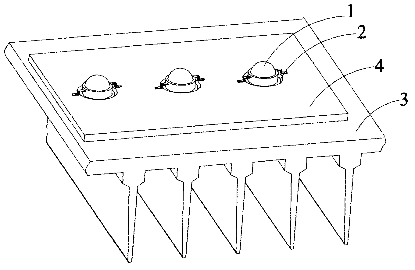
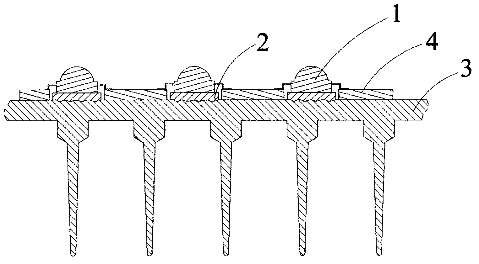
[0025] Such as figure 1 , figure 2 As shown, this embodiment is mainly composed of LED light source 1, metal layer 2, substrate 3, PCB board 4 and other components. Among them, the metal layer 2 is thermally sprayed on the surface of the substrate 3, and the PCB board 4 is installed on the surface of the metal layer 2 and the substrate 3. There are many openings in the middle of the PCB board 4, and the aperture is slightly larger than the size of the bracket of the LED light source 1. The LED The light source 1 is installed in the opening of the PCB 4 and welded on the metal layer 2 , and the pins at both ends of the LED light source 1 are welded on the PCB 4 to form a connection with the circuit distribution on the PCB 4 .

[0026] During the spraying process of the metal layer 2, for the selection of the thermal spraying position on the surface of the substrate 3, local fixed-point spraying or full spraying can be adopted. All thermal spraying is adopted. On the one hand...

Embodiment 2

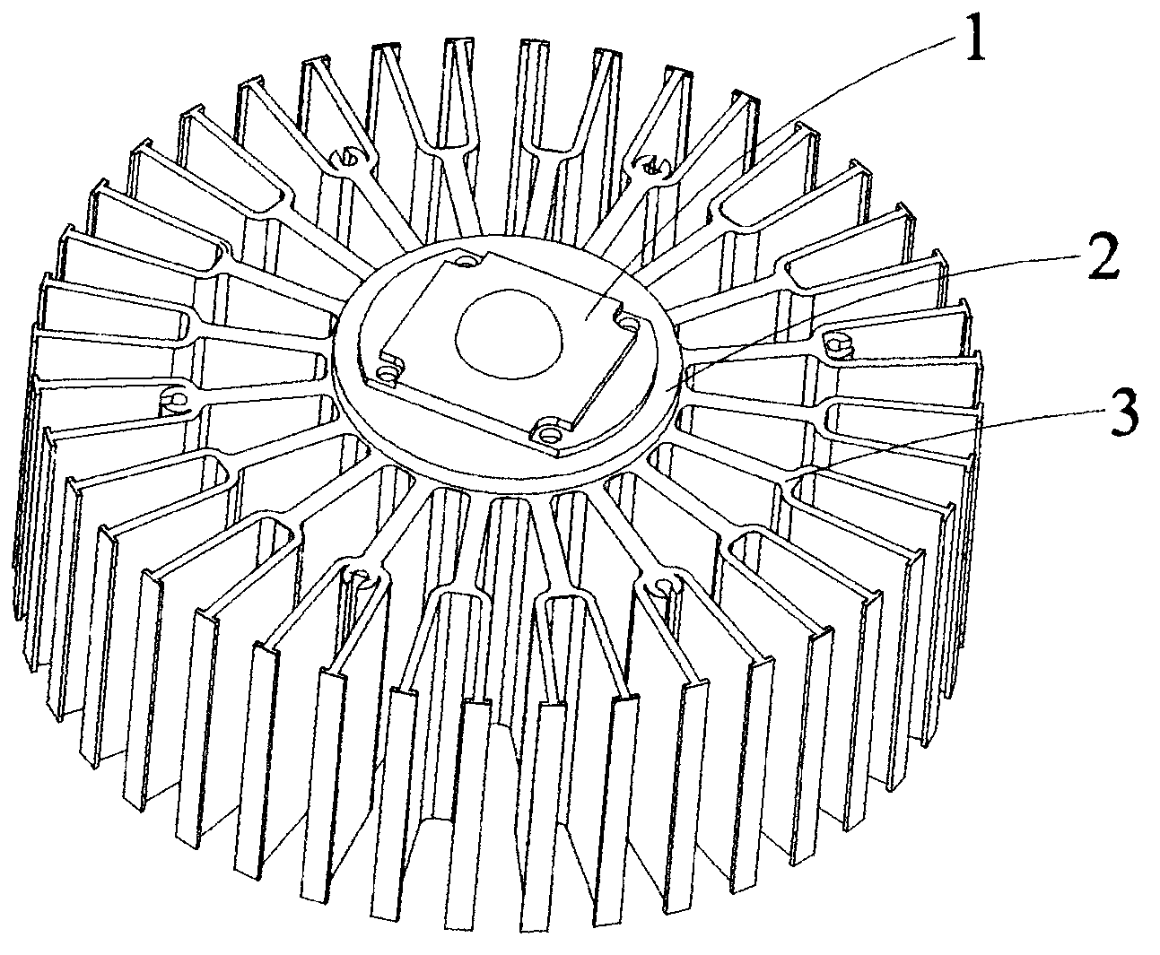
[0037] Such as image 3 and Figure 4 , this preferred embodiment is mainly composed of LED light source 1, metal layer 2, substrate 3 and so on. Wherein, the base plate 3 adopts an aluminum alloy heat sink with a structure similar to a sunflower, and the central part is a solid cylinder with cooling fins radially distributed around the cylinder. The metal layer 2 is thermally sprayed on the entire cylinder plane on the substrate 3 , and the integrated packaged LED light source 1 is welded on the surface of the metal layer 2 .

[0038] As the main part of heat dissipation, the substrate 3 can be changed according to actual application needs. It can be considered that the surface of the component that plays a role in heat dissipation can be used as the substrate 3 for thermal spraying of the metal layer 2 on the surface. The substrate 3 in this implementation adopts a heat sink similar to a sunflower structure. On the one hand, it has a wide range of applications and can be u...


PUM


Abstract

The invention discloses a welding type LED substrate and a manufacturing technology thereof. The welding type LED substrate comprises an LED light source and a substrate body. The surface of the substrate body is coated with a metal layer in a hot spraying mode. The LED light source is welded to the metal layer. The substrate body can be the bottom of an outer shell or a plane panel or a heat dissipating device with a cooling fin. According to the manufacturing technology of the welding type LED substrate, firstly, the surface of the substrate body is coated with the metal layer in the hot spraying mode, and secondly, the LED light source is fixed on the metal layer based on the welding technology. Compared with mechanical contact of existing heat conducting glue filling, the welding type LED substrate has the advantages that the LED light source direct welding method is adopted, the LED light source is fixed on the metal layer of the heat dissipating device, the heat conducting middle transition of an aluminum substrate is omitted, and the welded light source is higher in strength and better in stability. The metal layer is generally made of copper and other high-thermal conductivity welding metal. The LED light source can directly transmit the heat to the metal layer after being welded, then the heat is transmitted to the heat dissipating device through the metal layer to be dissipated, the heat resistance is reduced to the maximum extent, the heat conducting efficiency is improved, and the light attenuation of the LED light source is reduced.

Description

technical field [0001] The invention relates to a novel LED substrate, in particular to a substrate whose surface can be directly welded with an LED light source and a manufacturing process thereof. Background technique [0002] Light-emitting diode (LED), as the fourth-generation green lighting source internationally recognized, has unique advantages such as energy saving, environmental protection, no radiation, long service life, fast response speed, and impact resistance. With the continuous improvement of LED performance, its application fields continue to With the expansion, the application power of the light source is also continuously increasing, and the resulting heat generation is also greatly increased. Due to the heat generated by LEDs, especially power-type LED light sources, or when multiple light sources are used at the same time, the heat is concentrated and continues to generate heat, so there are strict requirements for light source heat dissipation, which n...

Claims


Application Information

Patent Timeline
Patent Type & Authority Applications(China)
IPC IPC(8): F21V19/00F21V29/00F21Y101/02F21V29/76F21V29/77F21V29/89
CPCF21V19/00F21V29/00
Inventor 诸建平吴祖通
Owner ZHEJIANG GEMCORE TECH
Why Eureka
Try Eureka