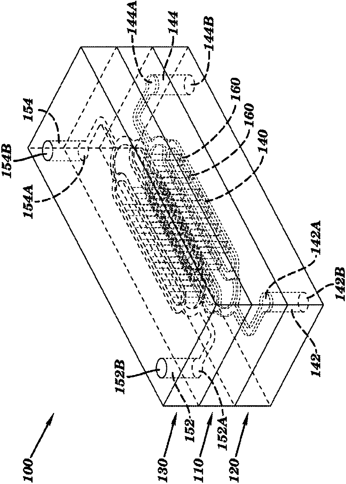
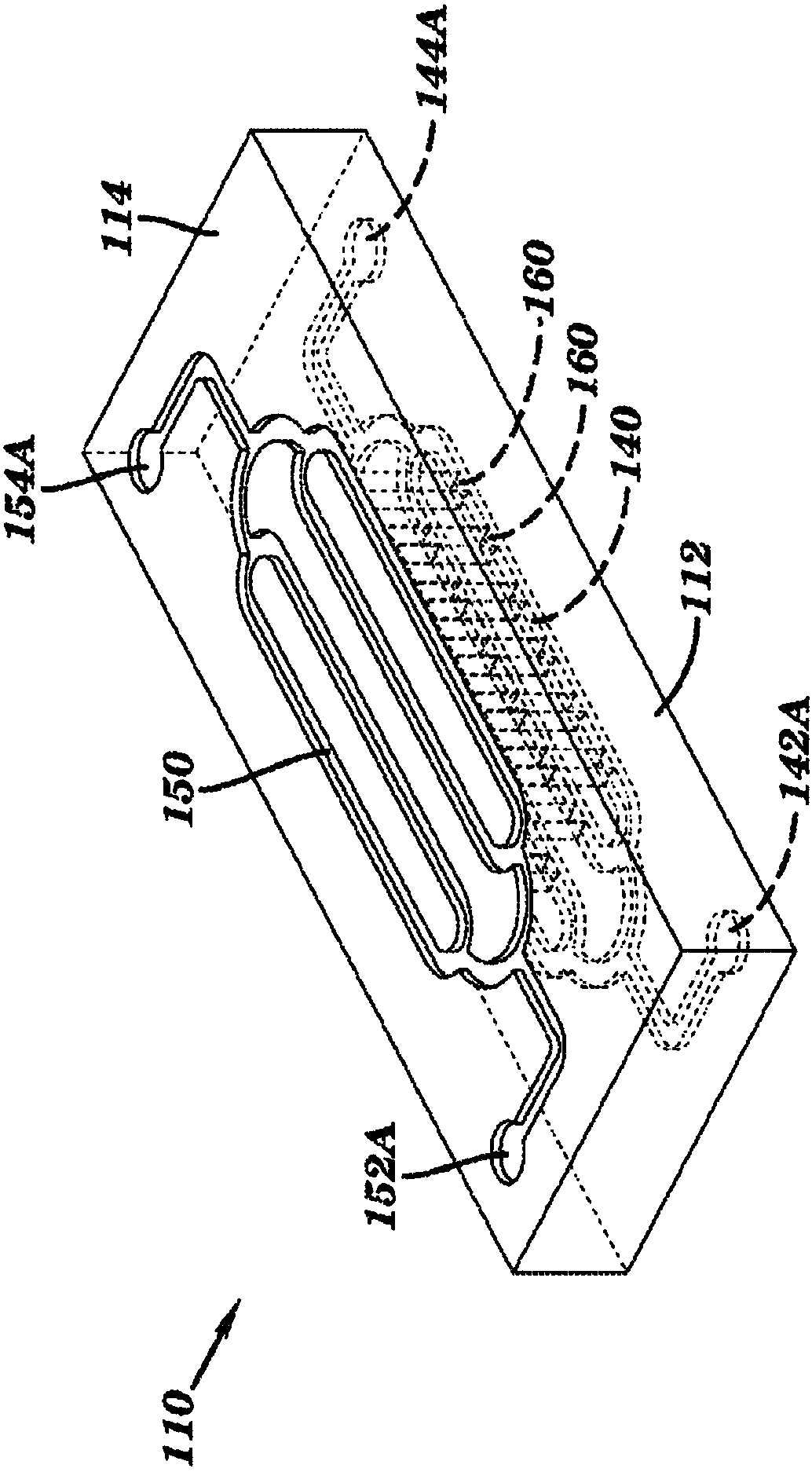
Dialysis like therapeutic (DLT) device
A microfluidic device and channel technology, applied in dialysis systems, injection devices, measurement devices, etc., can solve the problems of narrow ligand range and limited system capacity.
- Summary
- Abstract
- Description
- Claims
- Application Information
AI Technical Summary
Problems solved by technology
Method used
Image
Examples
Embodiment 1
[0399] Example 1: High flow microfluidic device
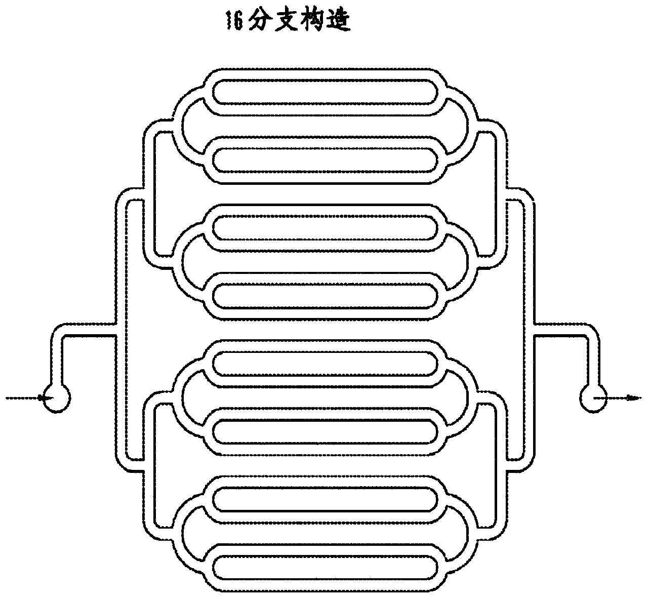
[0400] The microfluidic device is made of polysulfone, an FDA-approved blood-compatible material. The device is laminated from an optically clear film covered with adhesive on one side. The inventors have previously tested the capability of the device at high flow rates up to 360 mL / h; however, the blood perfusion time was short. Therefore, the present inventors circulated heparinized human whole blood collected from healthy human donors at flow rates of 100 mL / h and 200 mL / h for 2 hours ( FIG. 14 ). After circulating the blood through the device, the blood remaining in the channel was washed with PBS buffer. There are no blood clots formed by shear stress in the device. However, when circulating non-heparinized human whole blood through the device for 2 hours, the inventors found several large blood clots adhering to the channel surface. Applying an anticoagulant surface such as SLIPS to the device would address this issue...
Embodiment 2
[0403] Embodiment 2: sepsis animal model
[0404] The inventors modified the previous microfluidic device design to enhance the separation efficiency of pathogens bound to 1 μm MBL-conjugated magnetic beads. To take advantage of the high magnetic flux density gradient across the device to pull the bead-bound pathogens out, the inventors replaced the top and bottom polysulfone layers with a thin polymer membrane coated with an adhesive on one side, which Reduce the distance between the stationary magnet and the bottom blood channel through which bead-bound pathogens flow. Since the magnetic flux density gradient greatly decreases with increasing distance from the magnet, this improved preparation enables the exploitation of extremely strong magnetic forces near the magnet surface. In addition, computational modeling studies that provide more accurate estimates of magnetic field strength near magnets reveal that magnetic force can be improved by modifying the magnet's geometry....
Embodiment 3
[0410] Embodiment 3: Rat sepsis model
[0411] The inventors modified the microfluidic device and tubing setup to tune the microfluidic system to a rat sepsis model. The small blood volume in rats allows for a reduced volume of devices and tubing to prime with crystalloid solutions, thereby minimizing the dilution effect on the rat blood. A modified design of the device has a 1.2 mL blood channel network and 1 mL tubing, whereas the previous device enabled the blood channel network to perfuse 2.5 mL. Furthermore, in order to completely eliminate the air bubbles in the microfluidic system, the inventors added a bubble trapping device (#25014, www.restek.com) Integration with the DLT system ( Figure 18 ). Air bubbles that occur accidentally in the pipeline can be completely removed. If excess air bubbles get into the line, those bubbles can be removed through the three-way valve before the bubble trap.
PUM
| Property | Measurement | Unit |
|---|---|---|
| Thickness | aaaaa | aaaaa |
| Thickness | aaaaa | aaaaa |
| Length | aaaaa | aaaaa |
Abstract
Description
Claims
Application Information
 - R&D
- Intellectual Property
- Life Sciences
- Materials
- Tech Scout
- Unparalleled Data Quality
- Higher Quality Content
- 60% Fewer Hallucinations
Browse by: Latest US Patents, China's latest patents, Technical Efficacy Thesaurus, Application Domain, Technology Topic, Popular Technical Reports.
© 2025 PatSnap. All rights reserved.Legal|Privacy policy|Modern Slavery Act Transparency Statement|Sitemap|About US| Contact US: help@patsnap.com


