Fracture reduction lifting needle

A needle bar and clamping part technology, applied in the field of fracture reduction and pulling needles, can solve the problems of delaying operation time, easy loosening, inconvenience to hold, etc., and achieve the effect of saving operation time, not easy to loosen, and comfortable to operate

Inactive Publication Date: 2014-07-09
闫军
View PDF11 Cites 3 Cited by
  • Summary
  • Abstract
  • Description
  • Claims
  • Application Information

AI Technical Summary

Problems solved by technology

However, due to the abundance of thigh muscles, the fracture end shifts significantly after the fracture. During the closed reduction process, due to the action of gravity, the distal end of the fracture shifts backward and may rotate at the same time.
Bringing difficulties to closed reduction, or even failure and changing to open reduction and internal fixation
[0003] The commonly used method is to insert a Kirschner wire or a Steiner wire into the distal end of the fracture to lift it. However, since the Kirschner wire or Steerer wire is not threaded, it is easy to loosen during the reset process, and the needle body is too soft to use force. Cannot be retracted for lateral displacement
The semi-threaded needle is too soft, and the disadvantages are the same as Kirschner wires and SS wires. The full-threaded needle is too hard to bend, and it is inconvenient to handle.
If the tip of the needle is too blunt, you need to use an electric drill to drill the hole first, and then screw it in, which delays the operation time and may have the disadvantage of insufficient holding force
However, relying solely on assistants to support with hands cannot last for a long time, hindering the operation of the main surgeon, etc.

Method used


Image

  • Fracture reduction lifting needle
  • Fracture reduction lifting needle
  • Fracture reduction lifting needle

Examples


Embodiment Construction

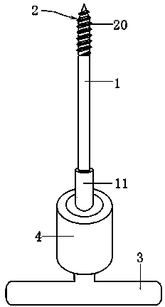
[0025] Such as figure 1 As shown, the present invention includes a needle bar 1 provided with a tip 2, the needle bar 1 is provided with a clamping part 4, one end of the clamping part 4 is provided with a jack 5 matching the tail of the needle bar 1, and the other end is provided with a handle 3, In order to facilitate handling during surgery, in this embodiment, the handle 3 is vertically connected to the clamping portion 4 , and the projection is T-shaped.

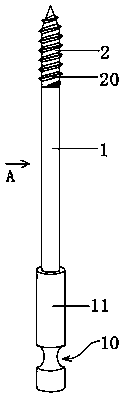
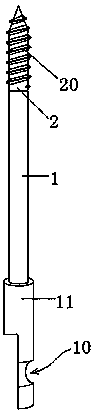
[0026] Thread 20 is provided on the needle shaft 1 at the end where tip 2 is provided. When using the lifting needle of the present invention, thread 20 can be easily drilled into the bone, and has a strong holding force, and is not easy to loosen during the reset operation. fall off. Of course, in order to increase the sharpness of the tip 2 and facilitate drilling into the bone, the tip 2 is in the shape of a triangular prism with a triangular cross-section.

[0027] Such as Figure 4 As shown, a jack 5 matching th...


PUM


Abstract

The invention discloses a fracture reduction lifting needle which comprises a needle bar with a tip. The needle bar is provided with a clamping portion, an insertion hole which is matched with the tail of the needle bar is formed in one end of the clamping portion, a handle is arranged at the other end of the clamping portion, threads are arranged at the end, where the tip is arranged, of the needle bar, buckles are arranged in the insertion hole, and a clamp groove which is matched with the buckles is formed in the tail of the needle bar. The cross section of the tip is triangular. The clamping portion comprises a core bar and a sleeve, the insertion hole is formed in the core bar, the sleeve sleeves the core bar, at least two through holes which are perpendicular to the insertion hole are formed in the middle of the core bar, and the buckles are collision beads which are inlaid in the through holes. The fracture reduction lifting needle has the advantages that the tip is prismatic, is high in sharpness and can be driven into the femoral cortical bone of a patient easily, and accordingly the operation time can be saved; a needle head is provided with the threads, so that the fracture reduction lifting needle is high in pullout strength, and is not easy to loosen or fall off during reduction operation.

Description

technical field [0001] The invention relates to a medical device, in particular to a fracture reduction and lifting needle. Background technique [0002] At present, adult femoral shaft displacement fractures are treated surgically, and femoral interlocking intramedullary nail fixation has become the preferred method. With the promotion of the concept of minimally invasive treatment, closed reduction femoral interlocking intramedullary nail internal fixation in the treatment of femoral shaft fractures has the advantages of less trauma, less bleeding, no periosteum stripping, no interference with the blood supply of the fracture end, fast fracture healing, and postoperative internal fixation failure. There are few complications. However, due to the rich muscle of the thigh, the fracture end shifts significantly after the fracture. During the closed reduction process, due to the action of gravity, the distal end of the fracture shifts backward and may rotate at the same time....

Claims


Application Information

Patent Timeline
Patent Type & Authority Applications(China)
IPC IPC(8): A61B17/56
CPCA61B17/56
Inventor 闫军
Owner 闫军
Why Eureka
Try Eureka