Lighting device and relative projection system thereof
A light-emitting device and excitation light technology, which is applied in projection devices, optics, optical components, etc., can solve the problem of insufficient uniformity of combined light
- Summary
- Abstract
- Description
- Claims
- Application Information
AI Technical Summary
Problems solved by technology
Method used
Image
Examples
Embodiment 1
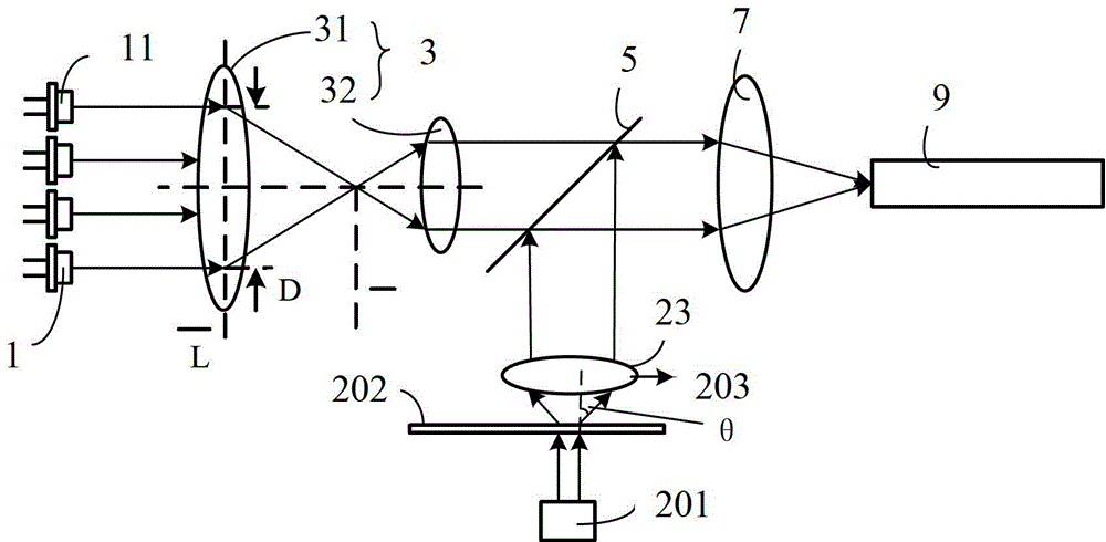
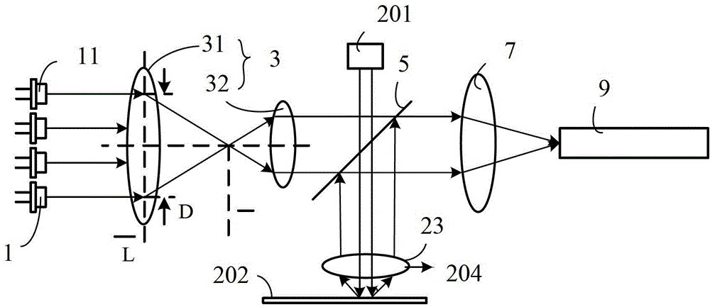
[0044] See Figure 2A , Figure 2A It is a structural schematic diagram of an embodiment of the light emitting device in the embodiment of the present invention. The light emitting device 200 includes an excitation light source 201, a wavelength conversion device 202 carrying a wavelength conversion material, a first collection device 203, a laser light source device 1, a second collection device 3, a wavelength combining device 5, a third collection lens 7 and a first homogenizer. light stick9.
[0045] The excitation light source 201 is used to generate excitation light. The laser light source 201 may be an LED or a laser diode, and is used to excite the wavelength conversion material in the wavelength conversion device 202 to generate the first color of the stimulated light. The most commonly used wavelength conversion material is phosphor, such as YAG phosphor, which can absorb blue light and be stimulated to emit yellow stimulated light. The wavelength conversion mater...
Embodiment 2
[0069] see Figure 5 , Figure 5 It is a structural schematic diagram of another embodiment of the light emitting device in the embodiment of the present invention. The light emitting device 500 includes an excitation light source 201, a wavelength conversion device 202 carrying a wavelength conversion material, a first collection device 203, a laser light source device 1, a second collection device 3, a wavelength combining device 5, a third collection lens 7 and a first homogenizer. light stick9.
[0070] The difference from the embodiments shown above is that in this embodiment, the laser light source array 11 in the laser light source device 1 includes a first laser light source array 51 and a second laser light source array 52 . The laser light source device 1 also includes a light combining device 53. The light emitted by the first laser array 51 is transmitted through the light combining device 53 to form transmitted light, and the light emitted by the second laser ar...
Embodiment 3
[0078] see Figure 8 , Figure 8 It is a structural schematic diagram of another embodiment of the light emitting device in the embodiment of the present invention. The light emitting device 800 includes an excitation light source 801 , a wavelength conversion device 802 carrying a wavelength conversion material, a first collecting device 803 , a laser light source device 2 , a second collecting device 4 , a wavelength combining device 6 and a first uniform rod 8 .
[0079] The difference between this embodiment and the above embodiment is:
[0080] In this embodiment, the first collection device 803 includes a collection lens 83 for collecting the received light emitted by the wavelength conversion device 802 . The shape of the received light after passing through the first collecting device 803 is a circular light cone, wherein the light cone angle of the circular light cone on the incident wavelength combining device 6 is θ2.
[0081] The second collecting device 4 inclu...
PUM
 Abstract
Description
Claims
Application Information
 - R&D
- Intellectual Property
- Life Sciences
- Materials
- Tech Scout
- Unparalleled Data Quality
- Higher Quality Content
- 60% Fewer Hallucinations
Browse by: Latest US Patents, China's latest patents, Technical Efficacy Thesaurus, Application Domain, Technology Topic, Popular Technical Reports.
© 2025 PatSnap. All rights reserved.Legal|Privacy policy|Modern Slavery Act Transparency Statement|Sitemap|About US| Contact US: help@patsnap.com


