Direct-current bus voltage buildup device based on double-active-bridge convertor and starting method thereof

A dual active bridge and DC bus technology, which is used in conversion devices and instruments that convert DC power input to DC power output and output power, can solve the problem of increasing system design costs, inability to meet low cost, and disadvantageous high power density, etc. problem, to achieve the effect of low cost, high reliability and easy selection

Active Publication Date: 2014-07-09
江苏博斯特新能源技术有限公司
View PDF6 Cites 16 Cited by
  • Summary
  • Abstract
  • Description
  • Claims
  • Application Information

AI Technical Summary

Problems solved by technology

Among them, both the flyback type and the buck type start-up method need to add additional hardware circuits, which increases the design cost of the system and is not conducive to the realization of high power density. Although the low-voltage side series resistor is simple in structure and low in cost, it is only suitable for In low-power occasions, when the power is high, it is necessary to connect a resistor with a higher power level in parallel, which results in a larger volume and greater energy consumption
Therefore, the existing start-up methods cannot meet the requirements of low cost, high efficiency and high power density in practical applications.

Method used


Image

  • Direct-current bus voltage buildup device based on double-active-bridge convertor and starting method thereof
  • Direct-current bus voltage buildup device based on double-active-bridge convertor and starting method thereof
  • Direct-current bus voltage buildup device based on double-active-bridge convertor and starting method thereof

Examples


Embodiment Construction

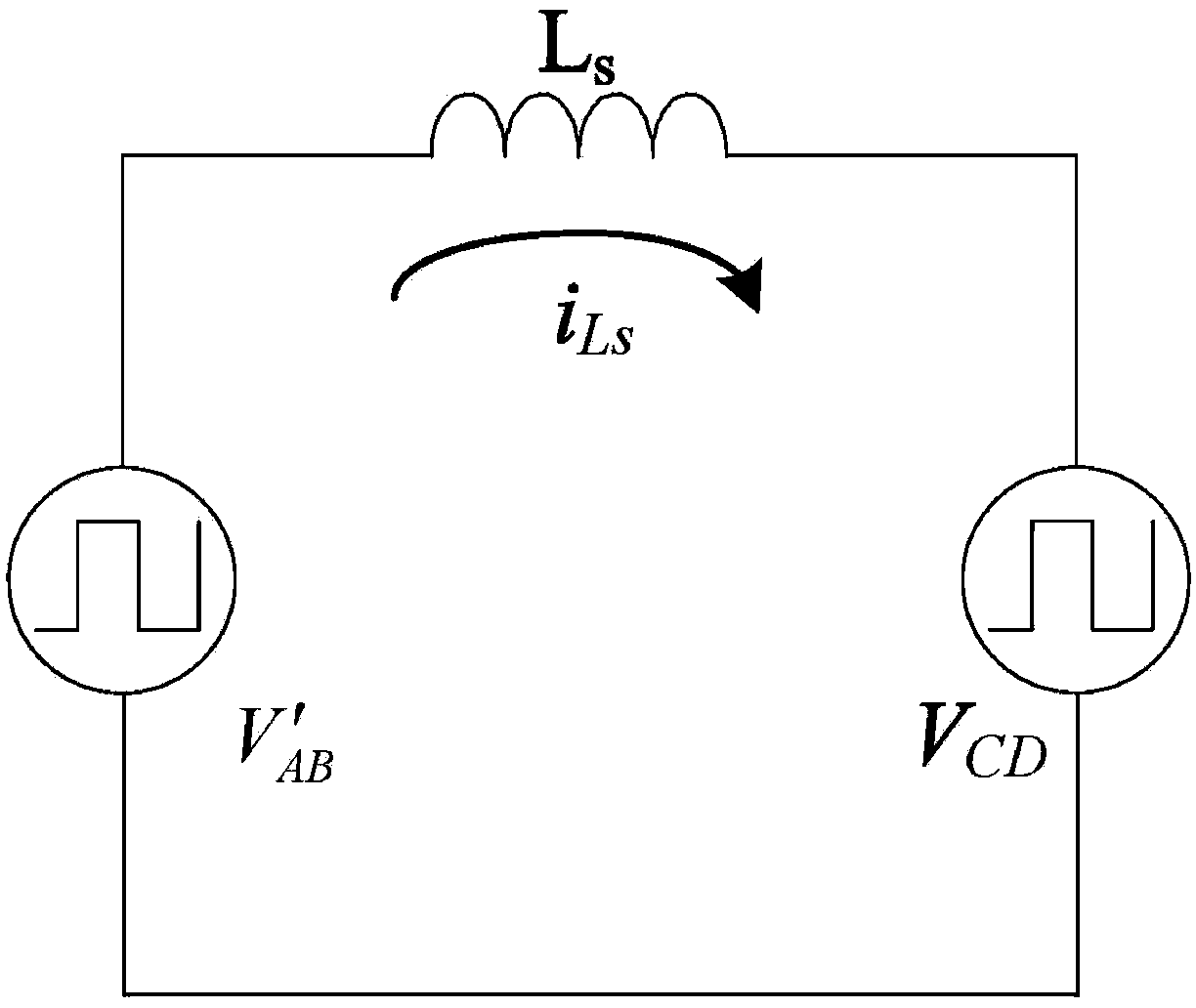
[0039] The present invention aims at the inductance saturation phenomenon that may occur in the resonant inductance when the voltage of the high-voltage side DC bus is built during the start-up process of the dual active bridge converter circuit, and the current impact problem caused by it, and proposes a switch tube based on the high-voltage side. Body diode rectification voltage build start method.

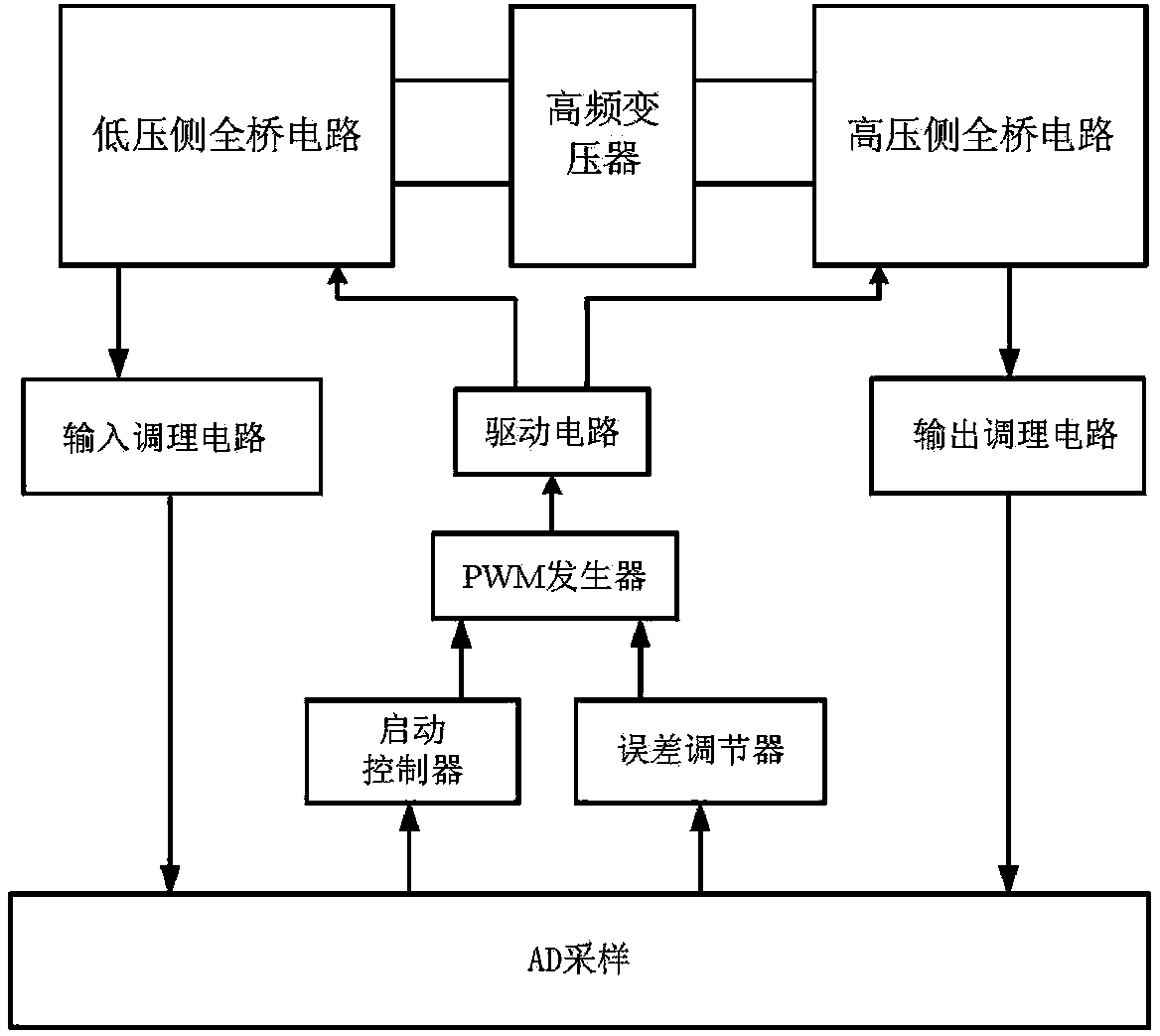
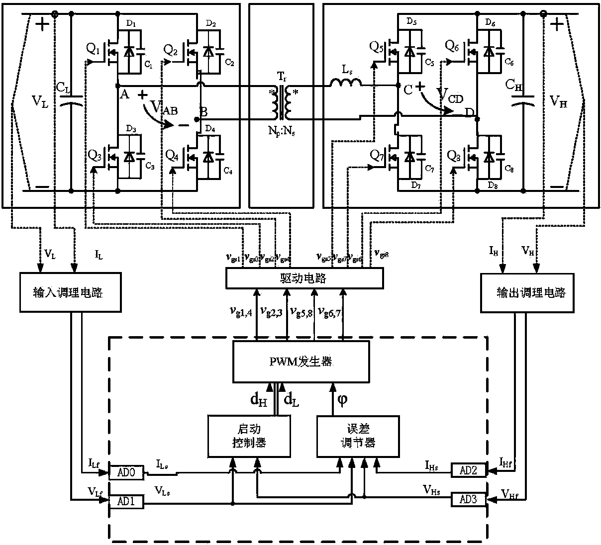
[0040] like figure 1 , 2 As shown, the present invention includes: a low-voltage side full-bridge circuit, a high-frequency transformer, a high-voltage side full-bridge circuit, an input conditioning circuit, an output conditioning circuit, an AD sampling unit, a starting controller, an error regulator, a PWM generator, and a drive circuit; Among them, the full-bridge circuit on the low-voltage side is connected to the high-frequency transformer and then connected to the full-bridge circuit on the high-voltage side to form a dual active bridge circuit; the A / D sampling unit, th...


PUM


Abstract

The invention discloses a direct-current bus voltage buildup device based on a double-active-bridge convertor and a starting method of the direct-current bus voltage buildup device in the field of electrical and electronic engineering. According to the direct-current bus voltage buildup device, input end sampled signals of a low-voltage-side full-bridge circuit are sent to a digital signal processor through an input conditioning circuit, output end sampled signals of a high-voltage-side full-bridge circuit are sent to the digital signal processor through an output conditioning circuit, the signal output end of the digital signal processor is connected with a driving circuit, and the driving circuit controls power tubes in the low-voltage-side full-bridge circuit and the high-voltage-side full-bridge circuit to be turned on/off. When a double-active-bridge circuit is started, a high-pressure-side switching tube is cut off, a low-pressure-side switching tube is driven through narrow pulses, and a capacitor on the high-pressure direct-current side is charged through a rectified body diode of the high-pressure-side switching tube to build up direct-current bus voltage. Inductance saturation in the direct-current bus voltage buildup process can be effectively avoided, the starting method does not need hardware cost, only digital control is needed to implement the starting method, hardware circuit cost is saved, and the direct-current bus voltage buildup device can be used in control over a two-way charger.

Description

technical field [0001] The invention relates to a dual active bridge converter, which belongs to the technical field of power electronics and electric engineering, and in particular to a DC bus voltage building device and a starting method for the dual active bridge converter. Background technique [0002] When the bidirectional charger works in the discharge mode, the dual active bridge is in the Boost state, and the energy flows from the low voltage side to the high voltage side. It is generally believed that the starting process of the dual active bridge should be the same as that of the traditional full bridge circuit, that is, control the switch on the low voltage side The conduction time of the tube gradually increases from zero, which can increase the voltage on the high-voltage side capacitor, but in fact, for the dual active bridge circuit, the above startup method is not feasible, because the moment the high-voltage side just starts The voltage on the capacitor is ...

Claims


Application Information

Patent Timeline
Patent Type & Authority Applications(China)
IPC IPC(8): H02M3/335
Inventor 方宇
Owner 江苏博斯特新能源技术有限公司
Why Eureka
Try Eureka