A chain link pin shaft automatic drilling and milling machine

A technology of automatic drilling and connecting pins, which is applied in the direction of metal processing machinery parts, clamping, supporting, etc., to solve the complex design of gas circuit and circuit installation, solve the problem of high labor intensity, and ensure the effect of product quality

Inactive Publication Date: 2016-02-10
肖闯
View PDF8 Cites 0 Cited by
  • Summary
  • Abstract
  • Description
  • Claims
  • Application Information

AI Technical Summary

Problems solved by technology

[0003] In order to solve the technical bottleneck of the current chain industry in this production link and to solve this backward production method, this technology has solved this problem very well and realized the fully automatic production process of parts processing, which would have required a large number of manual labor. operation, and the parts that need to be completed in multiple processes are completed at one time, which greatly improves the production efficiency and product quality. Installed on the rack table, the automatic drilling and milling machine includes a vibrating plate, a feeding guide rail, a cylinder, a clamping fixture, a milling platform mechanism, a center hole drilling mechanism, a small hole drilling mechanism, a chamfering mechanism, and an octagonal eight-station Turntable, precision cam divider, high-speed electric spindle mounting seat, high-speed electric spindle front and rear adjustment handwheel, material distribution mechanism, motor and automatic drilling and milling machine main body support, the main body support of the automatic drilling and milling machine is on the table of the rack, and the There is an octagonal eight-station turntable on the front side of the main body support of the automatic drilling and milling machine. There is a precision cam divider behind the octagonal eight-station turntable. There is a motor on the rear side of the main body support of the automatic drilling and milling machine. Connected with precision cam splitter;

Method used


Image

  • A chain link pin shaft automatic drilling and milling machine
  • A chain link pin shaft automatic drilling and milling machine
  • A chain link pin shaft automatic drilling and milling machine

Examples


Embodiment Construction

[0041] Below in conjunction with accompanying drawing and embodiment the invention is described in detail:

[0042] The invention solves this problem very well, realizes the fully automatic production process of parts processing, and completes the parts that originally required a large number of manual operations and multiple processes to complete at one time, greatly improving production efficiency and product quality.

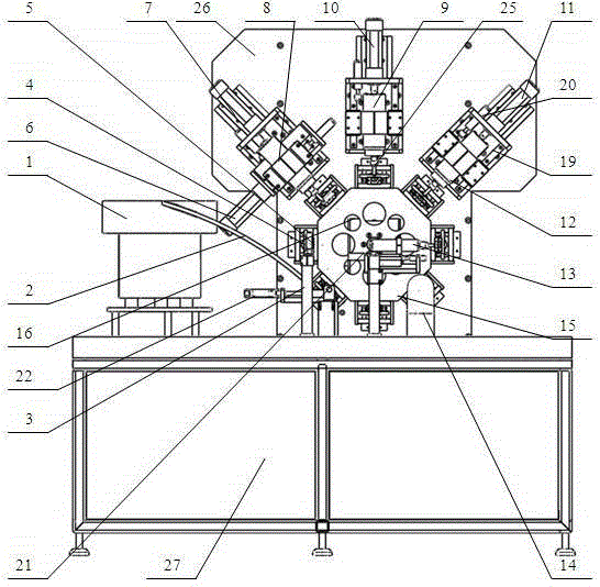
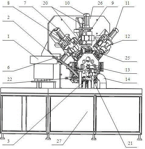
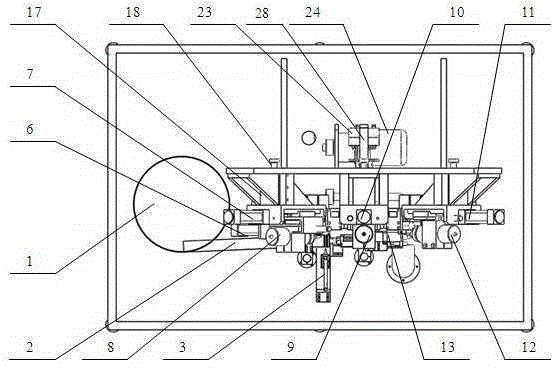
[0043]The specific working process of the technology of the present invention is: a vibrating plate installed on the left side of the equipment vibrates and arranges the pin shaft round rods to be processed into the feeding guide rail 2, and is separated by the material distribution mechanism 22 at the material inlet, and then is placed on the The material cylinder 3 is pushed into the facing clamping fixture 5, the octagonal eight-station turntable 15 rotates with the precision cam divider 16 driven by the motor 24, and the bar material is driven to the next ...


PUM


Abstract

An automatic drilling and milling machine for a chain connecting pin shaft is mounted on a rack table face, the automatic drilling and milling machine comprises a vibration disc, a feeding guide rail, an air cylinder, clamping jigs, a flat table milling mechanism, a central hole drilling mechanism, a small hole drilling mechanism, a chamfering mechanism, an octagonal eight-station rotating disc, a precise cam indexer, an electric motor and an automatic drilling and milling machine body support. The octagonal eight-station rotating disc is arranged on the front side of the automatic drilling and milling machine body support, the precise cam indexer is arranged behind the octagonal eight-station rotating disc, the electric motor is arranged on the rear side of the automatic drilling and milling machine body support, the electric motor is provided with a compressed air flow divider, the vibration disc is arranged on one side of the octagonal eight-station rotating disc, the eight clamping jigs are mounted on the octagonal eight-station rotating disc, the flat table milling mechanism, the central hole drilling mechanism and the small hole drilling mechanism are arranged on the upper side of the octagonal eight-station rotating disc, and the chamfering mechanism is mounted on the front side of the octagonal eight-station rotating disc. According to the technology, the full-automatic production process of part machining is achieved, and production efficiency and product quality are improved greatly.

Description

technical field [0001] The technology of the present invention relates to an automatic drilling and milling processing mechanical equipment for chain connecting pin shafts in the chain industry in the field of hardware machining, and is suitable for processing small holes and milling platforms for small pin shaft parts. Background technique [0002] At present, all large and medium-sized chain enterprises and related chain accessories processing enterprises in China use traditional drilling and milling equipment in the processing of the small holes of the chain connecting pins, and install some simple fixtures, which are manually processed by workers. . The production process is backward, the work efficiency is low (the average speed of mass production is about 15 seconds / piece), and the product quality is uneven (the deviation of the drilling size is large, exceeding 0.5mm). And each production enterprise needs a large number of workers to complete the processing work of t...

Claims


Application Information

Patent Timeline
Patent Type & Authority Patents(China)
IPC IPC(8): B23P23/00B23Q3/08B23Q7/00
CPCB23P23/02B23Q3/082B23Q7/02
Inventor 肖闯
Owner 肖闯
Why Eureka
Try Eureka