Thin film strainometer and preparation method thereof

A strain gage and thin film technology, applied in the field of thin film strain gage and its preparation, can solve the problems of weak anti-oxidation ability, functional layer oxidation failure, peeling, etc., and achieve the effects of improving anti-oxidation ability, improving adhesion strength and prolonging service life

Inactive Publication Date: 2014-07-16
UNIV OF ELECTRONICS SCI & TECH OF CHINA
View PDF4 Cites 6 Cited by
  • Summary
  • Abstract
  • Description
  • Claims
  • Application Information

AI Technical Summary

Problems solved by technology

However, Al prepared by electron beam evaporation method 2 o 3 There are inevitably conduction channels in the thin film, and it is impossible to completely isolate the functional layer of the strain gauge from the environment. In a long-term high-temperature environment, the failure phenomenon caused by the oxidation of the material of the functional layer of the strain gauge is still serious.
Therefore, the thin film strain gauges currently used have the following defects: First, the commonly used functional layer materials of thin film strain gauges, such as NiCr, PdCr, and TaN, are easily oxidized at high temperatures, making the thin film strain gauges weak in oxidation resistance under long-term high-temperature tests. Oxidation failure of the functional layer, reliability, service life, and stability cannot meet the requirements of high-temperature strain tests; second, in a long-term high-temperature environment, due to the different thermal expansion coefficients of the functional layer material and the transition layer material, it is easy to fall off , which in turn affects the service life of the thin film strain gauge; the third is the traditional method of evaporating Al on the surface of the functional layer 2 o 3 protective layer, due to the evaporated Al 2 o 3 There is inevitably a conduction channel in the thin film, so that the thin film strain gauge has a serious failure phenomenon due to the oxidation of the strain gauge functional layer material in a long-term high-temperature environment

Method used


Image

  • Thin film strainometer and preparation method thereof
  • Thin film strainometer and preparation method thereof
  • Thin film strainometer and preparation method thereof

Examples


Embodiment

[0027] Embodiment: a kind of preparation method of film strain gauge, comprises the following steps:

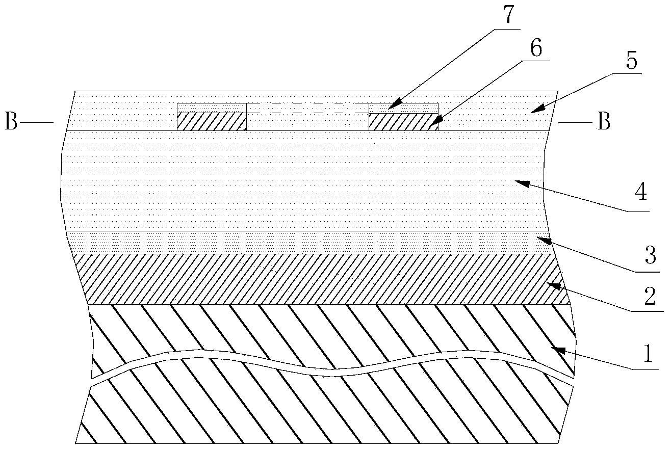
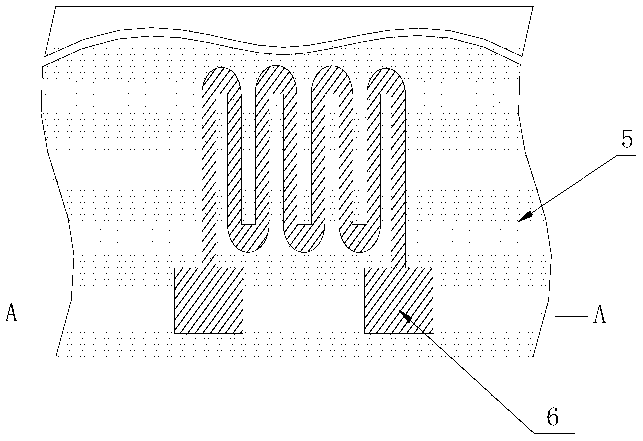
[0028] Step 1: Surface treatment of the alloy substrate: a nickel (Ni)-based alloy plate of (length×width×thickness) 30×95×5mm is used as the alloy substrate 1 to be tested, and acetone, ethanol and deionized water are used successively for the alloy substrate to be tested Clean the surface, and dry it with nitrogen after cleaning;

[0029] Step 2: Deposit a NiCrAlY alloy transition layer on the alloy substrate: place the cleaned Ni-based alloy substrate 1 in a vacuum of 5.0×10 -4 Pa vacuum (back vacuum) environment, with Ni 67 Cr 22 Al 10 Y alloy is used as the target material, and argon gas with a purity of 99.999% (volume percentage) is introduced as the sputtering medium. Under the conditions of temperature of 500°C, power of 500W, and sputtering pressure (working pressure) of 0.3Pa, DC magnetron is used. The NiCrAlY alloy is deposited on the Ni-based alloy substrate ...


PUM

PropertyMeasurementUnit
thicknessaaaaaaaaaa

Abstract

The invention provides a thin film strainometer and a preparation method thereof. The preparation method comprises the following steps: carrying out surface treatment on an alloy substrate; depositing a NiCrAlY transit layer on the alloy substrate; preparing an Al2O3 coupling layer; arranging an Al2O3 ceramic insulating layer; arranging a thin film strainometer function layer, arranging a thermal oxidation Al2O3 protective layer and finally arrange an Al2O3 ceramic protective layer. According to the thin film strainometer and the preparation method thereof, NiCrAlY alloy is adopted as a function layer, and the Al2O3 protective layer formed on the surface of the NiCrAlY alloy through aluminum separation and oxidation is more dense and stable, so that good protection of the thin film strainometer function layer is achieved; the function layer and the transit layer both adopts the same NiCrAlY alloy material and treatment technique, have the same thermal expansion coefficient and are not likely to fall off under high temperature work environment; the temperature strain does not occur, and the service life of the thin film strainometer is prolonged.

Description

technical field [0001] The invention belongs to the technical field of thin-film sensor design and production, and in particular relates to a thin-film strain gauge made by using a turbine engine blade to be tested as a substrate and a preparation method thereof. Background technique [0002] In modern aero-engine technology, the blade is the core component of the turbine engine. When the turbine engine is running, due to the high-speed operation of the blades and the combustion of fuel, high temperature and high pressure will be generated in the engine. Therefore, the blades will be subjected to comprehensive effects such as high centrifugal force, thermal stress, high vibration, and high temperature during operation, which will easily damage the blades and cause the engine to malfunction. Among the many factors that cause damage to the blades, vibration has a greater impact on the blades, and most of the faults caused by damage to the blades are caused by excessive vibrat...

Claims


Application Information

Patent Timeline
Patent Type & Authority Applications(China)
IPC IPC(8): B32B15/04B32B9/04B32B18/00G01B7/16
Inventor 蒋书文张洁蒋洪川张万里
Owner UNIV OF ELECTRONICS SCI & TECH OF CHINA
Why Eureka
Try Eureka