Shale gas well CO2 and slickwater mixing fracturing technology

A shale gas well, CO2 technology, applied in the direction of wellbore/well components, production fluid, earthwork drilling and production, etc., can solve the problems of low flowback speed and flowback efficiency, increased cost, and high difficulty, so as to reduce the reservoir Damage, increase flowback speed and flowback rate, and reduce construction difficulty

Active Publication Date: 2014-07-16
RES INST OF SHAANXI YANCHANG PETROLEUM GRP
View PDF3 Cites 51 Cited by
  • Summary
  • Abstract
  • Description
  • Claims
  • Application Information

AI Technical Summary

Problems solved by technology

[0004] Chinese invention (CN102852508A) proposes a liquid CO 2 Although the fracturing process solves the problems of high damage to shale gas reservoirs, low flowback speed and flowback efficiency of the slick water fracturing process, the use of liquid CO 2 Durin

Method used


Image

  • Shale gas well CO2 and slickwater mixing fracturing technology

Examples


Embodiment 1

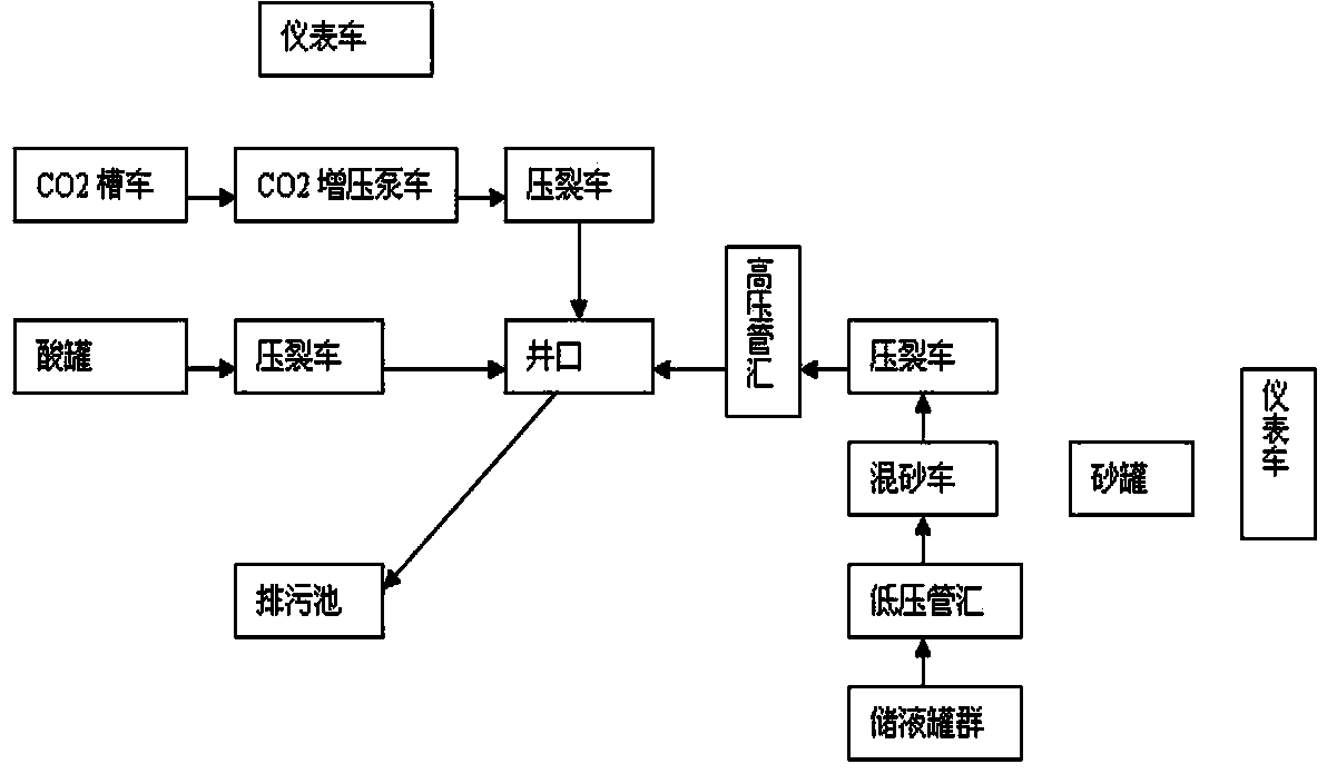
[0043] Shale gas well CO 2 and slick water mixed fracturing technology, the construction needs to be equipped with fracturing trucks, sand mixing trucks, CO 2 Tanker and CO 2 Pump trucks, instrument trucks, fracturing manifold trucks, acid tanks and liquid storage tank groups, the fracturing manifold trucks are equipped with low-pressure manifolds and high-pressure manifolds, and the instrument trucks are equipped with monitoring instruments, which are characterized in that: Follow the steps below:

[0044] Step 1: Prepare well site planning; place CO 2 Tank car and CO 2 The booster pump truck and the fracturing truck are connected in series to the wellhead, and the liquid storage tanks, low-pressure pipes, sand mixing truck, fracturing truck, and high-pressure manifold are connected in series to the wellhead; the acid tank and the fracturing truck are connected to the wellhead ;The wellhead is equipped with a blowout pipeline; the instrument vehicle is connected to the ab...

Embodiment 2

[0071] XX shale gas well, with a target interval of 2440.00-2490.00m, is black shale in the Shan 1 member of the Shanxi Formation. The logging gas log shows obvious results, which is comprehensively interpreted as a shale gas layer, and there is no productivity after perforation. The well uses CO 2 And slick water mixed fracturing process fracturing.

[0072] Step 1: If figure 1 Connect fracturing equipment and pipelines and prepare acid and fracturing fluid.

[0073] The fracturing method using bare casing injection, using P110 steel grade casing, the outer diameter of the casing is 51 / 2"; 10.0 m of acid liquid is prepared before fracturing 3 , the formula is 5.0% HCl + 8% high-efficiency pressure-reducing agent + 0.3% corrosion inhibitor + 0.2% iron ion stabilizer, equipped with slippery water fracturing fluid 2000 m 3 , the formula is clear water + 0.05% drag reducing agent + 1.5% clay stabilizer + 0.4% drainage aid + 0.3% gas well foaming agent + 0.05% fungicide. Prepa...


PUM

PropertyMeasurementUnit
Particle sizeaaaaaaaaaa

Abstract

The invention discloses a shale gas well CO2 and slickwater mixing fracturing technology, and relates to the technical field of shale gas exploiting, in particular to the mixing fracturing technology by adopting CO2 and slickwater. In the construction process, a fracturing truck, a fracturing blender truck, a CO2 tank truck, a CO2 pump truck, a measuring truck, a fracturing manifold truck, an acid tank, propping agents and a liquid storage pot group need to be prepared, the fracturing manifold truck is provided with a low-pressure manifold and a high-pressure manifold, and the measuring truck is provided with a monitoring instrument, and the technology is characterized by comprising seven steps of doing well site planning, pressure testing, acid liquid processing, CO2 fracturing construction, slickwater fracturing construction, well closing after fracturing, and flow opening and flowback after fracturing. The shale gas well CO2 and slickwater mixing fracturing technology has the advantage that the shale gas exploiting method which is low in cost, low in relative construction difficulty, small in damage to a shale gas reservoir stratum and efficient is achieved.

Description

technical field [0001] The invention relates to the technical field of shale gas exploitation, in particular to a 2 and slick water mixed fracturing process. Background technique [0002] Shale gas refers to the natural gas that mainly exists in the interlayers of dark mudstone, high-carbon mudstone, shale and silty rock in an adsorbed or free state. Shale gas is different from conventional natural gas reservoirs. It is not only the source rock for natural gas generation, but also the reservoir and cap rock for accumulating and preserving natural gas. Due to its low porosity and low permeability, all shale gas wells usually need to be fractured. Transformation can be mined. [0003] At present, the fracturing method used in shale gas wells is mainly slick water large-scale fracturing. The slick water fracturing fluid system is mainly composed of chemical additives such as clean water, drag reducer, drainage aid, clay stabilizer, and fungicide. The water consumption of cr...

Claims


Application Information

Patent Timeline
IPC IPC(8): E21B43/26E21B43/267E21B43/27
Inventor 王香增高瑞民申峰吴金桥郭庆张军涛乔红军高志亮段玉秀丁昊明梁小兵孙晓景丰
Owner RES INST OF SHAANXI YANCHANG PETROLEUM GRP
Why Eureka
Try Eureka