U-waveband high-power picosecond pulse laser generating method

A picosecond pulse and generation method technology, which is applied to lasers, laser components, and lasers using scattering effects, etc., can solve problems such as power boost limitations

Inactive Publication Date: 2014-07-16
HUNAN UNIV
View PDF5 Cites 3 Cited by
  • Summary
  • Abstract
  • Description
  • Claims
  • Application Information

AI Technical Summary

Problems solved by technology

Due to the high peak power of picosecond pulses, Raman fiber lasers using si

Method used


Image

  • U-waveband high-power picosecond pulse laser generating method
  • U-waveband high-power picosecond pulse laser generating method

Examples


Embodiment 1

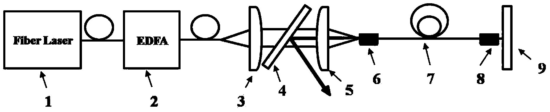
[0025] figure 1 It is a schematic diagram of a typical U-band tunable high-power picosecond pulse laser generation method. Including: a tunable picosecond pulse single-mode fiber laser seed source 1 working in the communication band (1520-1570nm); a common erbium-doped fiber amplifier (EDFA) 2; collimator lens 3; 45-degree placed pair 1520 -Dichroic mirror with high transmittance (>95%) for 1570nm pump light and high reflection for 1620-1680nm laser (reflectivity>99.8%); focusing lens 5; aluminum heat sink 6; standard multimode fiber / double cladding Optical fiber 7; aluminum heat sink 8; dichroic mirror 9 with high transmittance (>95%) for 1520-1570nm pump light and high reflection (reflectivity>99.8%) for 1620-1680nm. The incident end face of the multimode optical fiber / double-clad optical fiber 7 is cut vertically at 90 degrees, and together with the dichroic mirror 9 constitutes an optical resonant cavity for Raman laser with a wavelength of 1645nm. The generated U-band R...

Embodiment 2

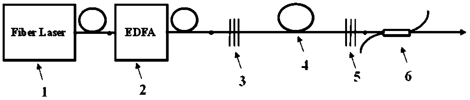
[0027] Such as figure 2 Shown, the difference between this embodiment and embodiment 1 is:

[0028] Embodiment 1 is a spatial Raman fiber laser, and Embodiment 2 is a Raman fiber laser with an all-fiber structure. Including: a picosecond pulse single-mode fiber laser seed source 1 working in the 1520-1570nm communication band; an erbium-doped fiber amplifier (EDFA) 2; fiber Bragg grating (FBG) 3; ordinary multimode fiber / double cladding optical fiber 4; fiber Bragg grating (FBG) 5; wavelength division multiplexer 6. The FBG3 and 5 together constitute the optical resonant cavity of the first-order Raman laser. The generated first-order Stokes Raman laser is output by the wavelength division multiplexer 6 .


PUM

PropertyMeasurementUnit
Diameteraaaaaaaaaa
Diameteraaaaaaaaaa

Abstract

The invention discloses a work U-waveband high-power picosecond pulse laser generating method. According to the method, a model locking picosecond pulse seed laser on the communication waveband is amplified through an erbium-doped optical fiber amplifier (EDFA) to obtain a high-power picosecond pulse laser, the output picosecond pulse laser is coupled to a regular multimode fiber or a double-clad fiber, and then picosecond pulse laser output is obtained through intra-resonant cavity feedback; the U-waveband Raman laser with a picosecond-magnitude pulse width is obtained by means of stimulated Raman frequency shift. There is no report currently about high-power picosecond or even shorter ultrafast pulses for lasers working on the wavelength. The high-power picosecond pulse laser output with the method is needed greatly in the aspects such as high-speed optical communication, Doppler anemometry laser radar, differential absorption laser radar and intermediate infrared lasers.

Description

technical field [0001] The invention relates to a method for generating a high-power picosecond pulse laser working in the U-band, in particular to a U-band high-power Raman fiber laser with a picosecond pulse width obtained by using stimulated Raman frequency shift and intracavity feedback . Background technique [0002] U-band (Ultralong band) lasers, that is, lasers in the eye-safe band with a wavelength of 1625-1675nm, have great potential in high-speed optical communications, Doppler wind lidar, differential absorption lidar, and mid-infrared laser generation. Application requirements. At present, the pulsed laser in this band is usually obtained by the optical parametric method, but the optical parametric method is complex and the power improvement space is limited. Through the same-band pumping method, that is, by pumping Er:YAG crystal or ceramics through a semiconductor laser (LD) with a wavelength of 1470nm or 1532nm, a laser with a wavelength of about 1.65μm can...

Claims


Application Information

Patent Timeline
IPC IPC(8): H01S3/30H01S3/067H01S3/11H01S3/17
Inventor 唐平华赵楚军张晗周蓉文双春
Owner HUNAN UNIV
Why Eureka
Try Eureka