Supercharge Your Innovation With Domain-Expert AI Agents!

Electro-gas welding technology suitable for thick plates with thickness ranging from 20 mm to 45 mm

A gas-electric vertical welding and thick plate technology, which is applied to arc welding equipment, manufacturing tools, welding equipment, etc., can solve the problems of difficult adaptation and matching, high cost, and complicated preparation work, so as to ensure the mechanical properties of the weld seam and save energy. Welding cost, better weld seam quality

Active Publication Date: 2014-07-23
武汉钢铁有限公司
View PDF4 Cites 9 Cited by
  • Summary
  • Abstract
  • Description
  • Claims
  • Application Information

AI Technical Summary

Problems solved by technology

However, if double-sided trapezoidal grooves are used, when welding the welds on the front side, cooling blocks or spacers need to be installed on the reverse side to form grooves in cooperation with the cooling blocks on the front side to prevent the welding liquid from flowing out; therefore, the cooling block must be installed Make it into a shape that matches the shape of the groove on the reverse side. Once the shape of the groove changes, the shape and size of the cooling block or pad must change accordingly; and whether it is processing the groove or the cooling block or pad There will be errors in each block, and it is more difficult to adapt and match the shape of the cooling block or pad and the reverse side groove, resulting in more complicated preparation work and high cost, and it is also prone to mismatch caused by machining errors. Gas-electric vertical welding process is unstable and inaccurate

Method used


Image

  • Electro-gas welding technology suitable for thick plates with thickness ranging from 20 mm to 45 mm
  • Electro-gas welding technology suitable for thick plates with thickness ranging from 20 mm to 45 mm
  • Electro-gas welding technology suitable for thick plates with thickness ranging from 20 mm to 45 mm

Examples


Embodiment Construction

[0028] The present invention will be further described in detail below in conjunction with the accompanying drawings and specific embodiments.

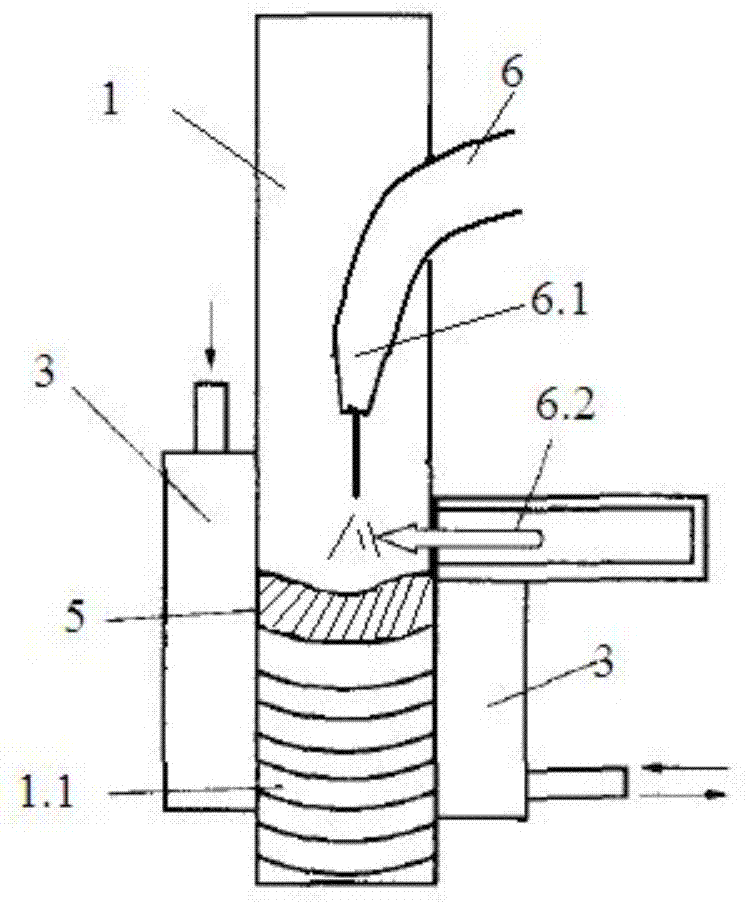
[0029] Figure 1~3 It is a schematic diagram of the traditional gas-electric vertical welding process, and its structure has been discussed above, so it will not be repeated here.

[0030] Such as Figure 4~6 As shown, the gas-electric vertical welding process suitable for 20~45mm thick plates designed by the present invention comprises the following steps:

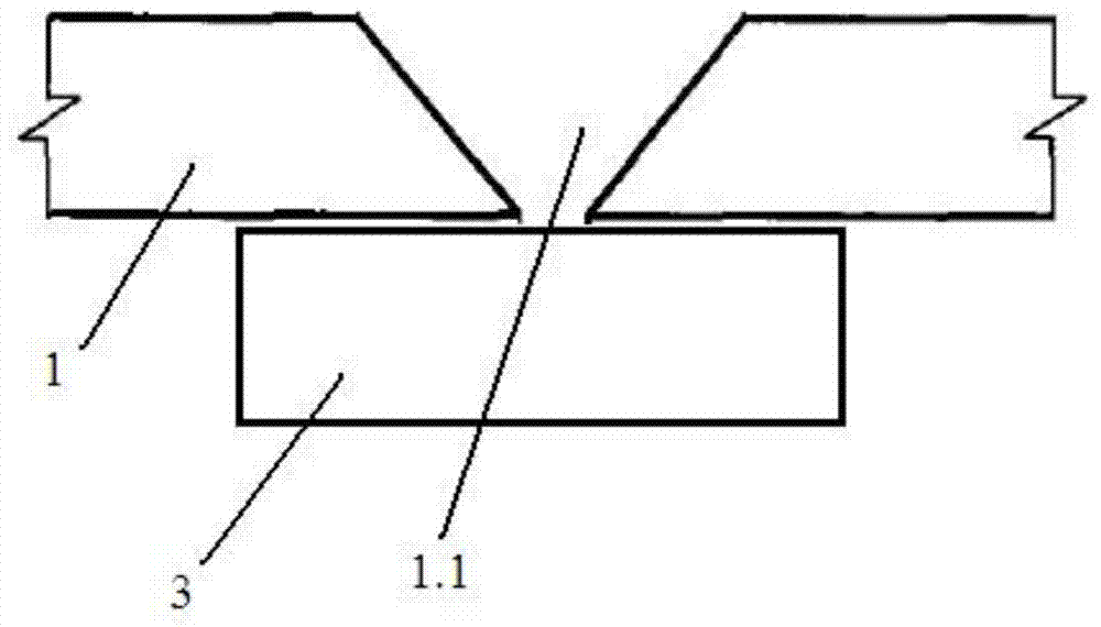
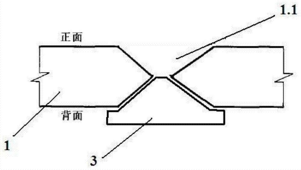
[0031] 1) First process sub-grooves on the front sides of the two thick plates 1 to be welded, and assemble the two thick plates 1 to be welded together according to the weld seam requirements, so that the sub-grooves on the front sides of the two thick plates 1 to be welded Combined to form trapezoidal front groove 2;

[0032] 2) Since there is no groove processed on the reverse side, it can play a role in forcing the welding liquid to form. If necessary, a cooling block 3 ca...


PUM

PropertyMeasurementUnit
Top widthaaaaaaaaaa

Abstract

The invention discloses an electro-gas welding technology suitable for thick plates with thickness ranging from 20 mm to 45 mm. The technology comprises the following steps that sub grooves are formed in the front surface sides of two thick plates to be welded respectively, the two thick plates to the welded are assembled together according to the weld joint requirement, and the sub grooves in the front surface sides of the two thick plates to be welded form a trapezoidal front surface groove in a combined mode; then electro-gas welding is performed on the trapezoidal front surface groove of the two thick plates to be welded, and a front surface weld joint is formed; a trapezoidal reverse surface groove opposite to the trapezoidal front surface groove is formed in the reverse surface sides of the two to-be-welded thick plates connected into a whole; finally, electro-gas welding or conventional arc welding is performed on the trapezoidal reverse surface groove of the thick plates to be welded, and welding of the thick plates with the thickness ranging from 20 mm to 45 mm is completed. The technology saves welding cost, reduces the phenomenon that the weld joint is polluted because a pad is melted in welding fluid, and guarantees the mechanical property of the weld joint. The technology is easy to implement, high in welding efficiency and good in quality of the weld joint.

Description

technical field [0001] The invention relates to welding technology in the field of metallurgy, in particular to a gas-electric vertical welding process suitable for 20-45mm thick plates. Background technique [0002] Gas-electric vertical welding (electro-gas welding) is a metal gas shielded arc welding method developed from common metal gas shielded welding and electroslag welding. The depth direction is at right angles. During welding, a copper slider is used on the front of the weld 1.1 of the weldment 1, and a water-cooled block or liner is used on the back of the weld. The flux-cored wire is fed into the groove formed by the weldment 1 and the block 3, and the molten pool 5 The four sides are constrained, and the weld 1.1 is forced to form at one time, such as figure 1 Its advantages are: high productivity and low cost. [0003] In the gas-electric vertical welding process, the welding input energy is an important parameter. The energy formula of the gas-electric ve...

Claims


Application Information

Patent Timeline
IPC IPC(8): B23K9/00B23K9/235
CPCB23K9/173B23K9/235
Inventor 黄治军陈浮胡家国郑江鹏
Owner 武汉钢铁有限公司
Features
  • R&D
  • Intellectual Property
  • Life Sciences
  • Materials
  • Tech Scout
  • Unparalleled Data Quality
  • Higher Quality Content
  • 60% Fewer Hallucinations
Learn More