Steam injection vacuum pumping system for power plant condenser with pressure control

A technology of vacuum pumping system and pressure control, applied in the field of vacuum pumping system, can solve the problems such as affecting the economical health and safe operation of the unit, unable to maintain the minimum vacuum of the condenser, and the temperature may reach more than 40 degrees, and reduce the consumption. Electricity cost, capacity improvement, effect of vacuum improvement

Active Publication Date: 2016-04-20
浦江瑞尔科技有限公司
View PDF5 Cites 0 Cited by
  • Summary
  • Abstract
  • Description
  • Claims
  • Application Information

AI Technical Summary

Problems solved by technology

[0004] 1. The water ring vacuum pump uses water as the working fluid. The temperature of the working fluid is controlled by the cooling water (circulating water or starting water). The temperature of the cooling water is affected by the climatic conditions, and the temperature changes greatly. Especially in summer, the temperature of the circulating water may reach More than 30 degrees, plus a certain heat transfer temperature difference, the temperature of the working fluid may reach more than 40 degrees. Under vacuum, a large amount of vaporization of the working fluid will cause cavitation and high noise of the vacuum pump, and the pumping capacity will decrease, making it impossible to maintain condensation. The minimum vacuum of the device has seriously affected the economical production and safe operation of the unit
[0005] 2. The power consumption of the water ring vacuum pump is high, and one or two water ring vacuum pumps need to be operated normally
[0006] 3. The water ring vacuum pump is a dynamic device, and the maintenance of the equipment is relatively large

Method used


Image

  • Steam injection vacuum pumping system for power plant condenser with pressure control

Examples


Embodiment Construction

[0055] In the following, specific implementation manners will be explained with reference to the concept of the present invention in conjunction with the accompanying drawings of the present application.

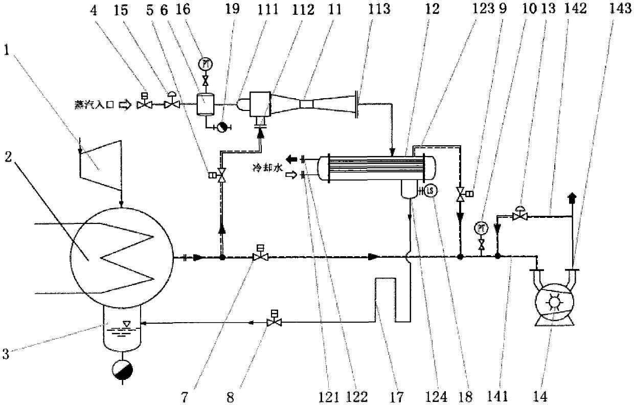
[0056] refer to figure 1 , in the power plant condenser steam injection vacuum pumping system with pressure control of the present invention, comprising:

[0057] Steam turbine 1, condenser 2, condenser hot well 3, power steam regulator 6, steam ejector 11, steam condenser 12, water ring vacuum pump 14, condensate drain valve of steam condenser 8, condensate Drain pipeline water seal 17, liquid level switch 18 of condensate pipeline, pressure regulating valve at the inlet of water ring vacuum pump, and multiple control valves and pipelines arranged between the above-mentioned components;

[0058] The outlet of the steam turbine 1 is connected to the inlet of the condenser 2; the first inlet 111 of the steam ejector is connected to the power steam surge tank 6, and the first o...


PUM


Abstract

The invention provides a power plant condenser steam jet and vacuumizing system with a pressure control function. The system comprises a steam turbine (1), a condenser (2), a condenser hot well (3), a power steam pressurizer (6), a steam ejector (11), a steam condenser (12), a water ring vacuum pump (14), a condensate discharge valve (8) of the steam condenser, a condensate drain pipeline water seal (17), a condensate pipeline liquid level switch (18), a pressure adjusting valve (13) on the inlet of the water ring vacuum pump, multiple control valves and pipelines, wherein the control valves and the pipelines are arranged among the parts. Due to the fact that pressure control of power steam, control of the liquid level after condensates flow back to the condenser hot well and inlet pressure control of the water ring vacuum pump are adopted, the vacuumizing system can maintain the maximum vacuum degree of the condenser, force of the condenser is improved, the vacuum degree of the condenser is improved, the heat consumption rate of the steam turbine is lowered, and coal consumption for unit power generation is lowered. The system is safe and free of maintenance, guarantees 100% of force and can operate stably for a long time. A pressure backflow adjusting system is arranged on the final-stage exhaust device, namely the water ring vacuum pump, so that it is guaranteed that the cavitation phenomenon of the water ring vacuum pump does not happen.

Description

technical field [0001] The invention relates to a vacuum pumping system in a power plant, in particular to a steam injection vacuum pumping system for a condenser of a power plant with pressure control. Background technique [0002] The condenser is one of the most important equipment in a power plant. The back pressure of the condenser has an important impact on the economy of the operation of the steam turbine generator set. The quality of the condenser vacuum of the condensing steam turbine generator set directly affects the steam turbine in the power plant economic operation. There are many factors affecting the vacuum of the condenser, including the system design arrangement related to the vacuum of the condenser, which affects the quality of the vacuum of the condenser. Multiple condensers have the advantages of reducing the heat consumption rate of the steam turbine unit, reducing the cooling area and cooling water volume, and improving the arrangement of the condens...

Claims


Application Information

Patent Timeline
Patent Type & Authority Patents(China)
IPC IPC(8): F28B9/10
Inventor 张曙光
Owner 浦江瑞尔科技有限公司
Why Eureka
Try Eureka