
Rapid vacuum desorption device and rapid vacuum desorption method for collecting volatile gas components in sample

A volatile gas and sample technology, applied in the field of desorption systems, can solve the problems of inability to quickly separate volatile components, incomplete separation of adsorbates, and difficulty in quantitative measurement, so as to eliminate sample cross-interference, prevent re-adsorption, and improve The effect of utilization

Inactive Publication Date: 2014-07-23
NANJING INST OF ENVIRONMENTAL SCI MINIST OF ECOLOGY & ENVIRONMENT OF THE PEOPLES REPUBLIC OF CHINA
View PDF9 Cites 14 Cited by
  • Summary
  • Abstract
  • Description
  • Claims
  • Application Information

AI Technical Summary

Problems solved by technology

[0006] Aiming at the defects of incomplete gas desorption, cumbersome operation, inability to realize quantitative volume measurement and easy cross-interference of samples in the prior art, the present invention provides a fast vacuum desorption method for collecting volatile gas components in samples. The device and its method, through high negative pressure control to ensure faster and more complete gas desorption process, and with residual gas volume correction, can solve the problem of inability to quickly separate volatile components in samples and incomplete separation of adsorbates , it is difficult to achieve quantitative measurement, and the equipment is not easy to be portable. It can effectively improve the gas desorption efficiency, have greater desorption capacity, reduce the monitoring cost, and have portability, which can monitor the application range

Method used


Image

  • Rapid vacuum desorption device and rapid vacuum desorption method for collecting volatile gas components in sample
  • Rapid vacuum desorption device and rapid vacuum desorption method for collecting volatile gas components in sample
  • Rapid vacuum desorption device and rapid vacuum desorption method for collecting volatile gas components in sample

Examples


Embodiment 1

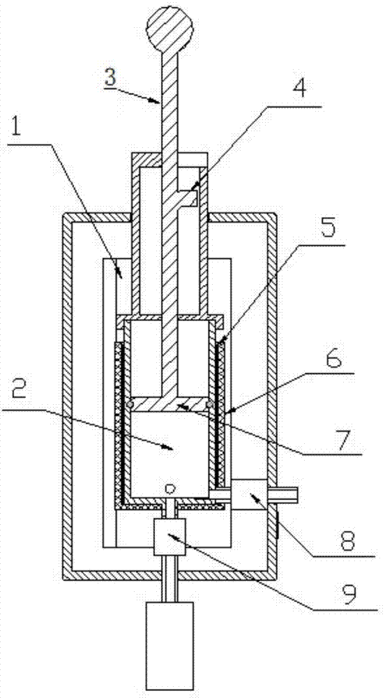
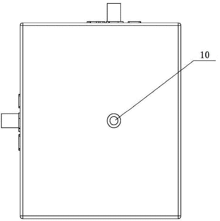
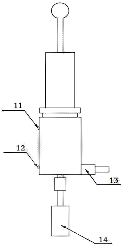
[0041] Such as Figure 1-6 As shown, a fast vacuum desorption device for the collection of volatile gas components in samples, including a suction cylinder 2 (piston cylinder), a suction piston 7 inside the suction cylinder 2 and an extension of it (suction piston) The piston handle 3 and the stop hook 4 between the two, the outer periphery of the suction cylinder 2 is wrapped by the heating layer 5 and the insulation layer 6, and there is an air inlet 10 connected to the air inlet solenoid valve 9 at the bottom of the air suction cylinder 2. The sample bottle 14 is screwed under the solenoid valve 9, and the gas washing port 16 and the gas outlet 17 connected to the gas washing solenoid valve 8 and the gas outlet solenoid valve 13 are respectively arranged on the bottom side of the air suction cylinder 2, and the gas washing solenoid valve 8 and the gas outlet solenoid valve 13 are respectively Connect the air washing port 16 and the air outlet 17 outside the casing; the uppe...


PUM


Abstract

The invention discloses a rapid vacuum desorption device and a rapid vacuum desorption method for collecting volatile gas components in a sample. The device comprises an air suction cylinder (2), an air suction piston (7), a piston handle (3) and a locking hanger (4), wherein the air suction piston (7) is arranged in the air suction cylinder (2), the piston handle (3) is arranged at the extended part of the air suction piston, and the locking hanger (4) is arranged between the air suction piston (7) and the piston handle (3); an air inlet (10) of an air inlet electromagnetic valve (9) is connected to the bottom of the air suction cylinder (2), a sample bottle is rotatably connected to the lower part of the air inlet electromagnetic valve (9), an air cleaning hole (16) and an air outlet (17) connected with an air-cleaning electromagnetic valve (8) and an air outlet electromagnetic valve (13) are respectively formed in the side face of the bottom of the air suction cylinder (2), and the air-cleaning electromagnetic valve (8) and the air outlet electromagnetic valve (13) are respectively connected with the air cleaning hole (16) and the air outlet (17) which are formed outside a shell; a display screen (15) and a main control board (1) are connected to the interior of the shell. The rapid vacuum desorption device is small in volume and is convenient to carry; the sample does not need to be subjected to complex pretreatment; the active volume of the volatile gas of the sample can be automatically calculated.

Description

technical field [0001] The invention relates to a desorption system for volatile components in solids and semi-solids, in particular to a fast vacuum desorption device for collecting volatile gas components in samples. Background technique [0002] Usually soil, charcoal, other adsorbents and other solids contain or absorb volatile components. After the sample needs to be crushed, add it to the sample bottle, add appropriate liquid, close the bottle, shake it well, and then heat the sample bottle. It is convenient for the volatilization of volatile substances, and then the gas containing volatile substances is extracted and analyzed by the analyzer. However, the operation of the method and equipment is cumbersome, and the volatile components cannot be easily analyzed. [0003] Chinese patent application number: 2011100664865, title of invention: a gas cylinder-type soil profile gas collector, which adopts technical features such as a vacuum pump, but has low negative pressu...

Claims


Application Information

Patent Timeline
IPC IPC(8): G01N1/22
Inventor 赵欣李杰林玉锁单艳红冯艳红应蓉蓉郑丽萍李建张胜田龙涛王国庆徐建田猛邓绍坡吴运金万金忠祝欣李群周艳
Owner NANJING INST OF ENVIRONMENTAL SCI MINIST OF ECOLOGY & ENVIRONMENT OF THE PEOPLES REPUBLIC OF CHINA
Learn More