Programmable gain amplifier

A programming gain and amplifier technology, applied in differential amplifiers, DC-coupled DC amplifiers, gain control, etc., can solve problems such as failure to work normally, amplifier output saturation, etc., to solve output saturation, increase common-mode rejection ratio, and suppress common-mode The effect of mode interference

Inactive Publication Date: 2014-07-23
CHANGSHA YUNTENG MICROELECTRONICS
View PDF4 Cites 11 Cited by
  • Summary
  • Abstract
  • Description
  • Claims
  • Application Information

AI Technical Summary

Problems solved by technology

As far as the CMOS process is concerned, the input offset voltage of the op amp is about 10mV, which is far greater than the useful physiological signal amplitude. In the case of high gain, the output of the amplifier is saturated due to the offset and cannot work normally.

Method used


Image

  • Programmable gain amplifier
  • Programmable gain amplifier
  • Programmable gain amplifier

Examples


Embodiment Construction

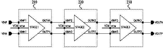
[0028] An embodiment of the programmable gain amplifier of the present invention is image 3 As shown, it includes a three-stage amplifying circuit: a first-stage amplifying circuit 210, a second-stage amplifying circuit 220, and a third-stage amplifying circuit 230; the non-inverting input VINP1 of the first-stage amplifying circuit 210 is connected to the input signal VINP, and the inverting input VINN1 is connected to the input signal VINN to form a pair of differential input terminals; the non-inverting input VINP2 of the second-stage amplifying circuit 220 is connected to the inverting output OUTN1 of the first-stage amplifying circuit 210, and the inverting input VINN2 is connected to the inverting output of the first-stage amplifying circuit 210 Non-inverting output OUTP1; the non-inverting input VINP3 of the third-stage amplifying circuit 230 is connected to the inverting output OUTN2 of the second-stage amplifying circuit 220, and the inverting input VINN3 is connected...


PUM


Abstract

The invention discloses a programmable gain amplifier which comprises three levels of amplifying circuits. The same-phase input end and the opposite-phase input end of the first-level amplifying circuit serve as the same-phase input end and the opposite-phase input end of the programmable gain amplifier respectively and form a pair of differential input ends of the programmable gain amplifier; the same-phase input end of the second-level amplifying circuit is connected with the opposite-phase output end of the first-level amplifying circuit, and the opposite-phase input end of the second-level amplifying circuit is connected with the same-phase output end of the first-level amplifying circuit; the same-phase input end of the third-level amplifying circuit is connected with the opposite-phase output end of the second-level amplifying circuit, and the opposite-phase input end of the third-level amplifying circuit is connected with the same-phase output end of the second-level amplifying circuit; the same-phase output end and the opposite-phase output end of the third-level amplifying circuit form a pair of differential output ends. The programmable gain amplifier can be used for amplifying micro physiological signals in the field of medical electronics so that high-precision gain can be achieved; meanwhile, adjustment can be achieved within a certain gain dynamic range, and the requirement for different amplitudes of input signals is met.

Description

technical field [0001] The invention belongs to integrated circuit amplifiers, in particular to a programmable gain amplifier. Background technique [0002] In the field of medical electronics, various physiological signals of the human body need to be detected or monitored in clinical diagnosis or medical research, such as blood pressure, heart rate, blood sugar, compound action potential generated by nerve contraction, and so on. figure 1 Shown is a multi-channel detection system, including: a multi-channel selection switch (MUX) 100 , a programmable gain amplifier (PGA) 200 , an analog-to-digital converter (ADC) 300 , and a digital processing unit (DIGITAL) 400 . MUX100 selects one input signal from multiple channels and sends it to PGA200. PGA200 amplifies the input signal to match the input range of ADC300. ADC300 converts the amplified analog signal into a digital signal and sends it to DIGTIAL400 for storage, analysis, deal with. [0003] These human physiological s...

Claims


Application Information

Patent Timeline
IPC IPC(8): H03G3/20H03F3/45
Inventor 马剑武刘文用
Owner CHANGSHA YUNTENG MICROELECTRONICS
Why Eureka
Try Eureka