
A remote monitoring system and method for fatigue cracks in orthotropic steel bridge decks

A steel bridge deck, orthotropic technology, applied in transmission systems, measuring devices, material analysis by optical means, etc., can solve the problem of inability to accurately determine the position of the crack tip, inability to reach fatigue cracking sensitive areas, and inaccessible areas to the operating space. and other problems, to achieve the effect of convenient and flexible placement, simplified monitoring workload, and multi-point monitoring.

Active Publication Date: 2017-10-31
SHANGHAI JIAOTONG UNIV
View PDF5 Cites 0 Cited by
  • Summary
  • Abstract
  • Description
  • Claims
  • Application Information

AI Technical Summary

Problems solved by technology

There are many limitations in the visual inspection method. For example, on-site conditions may make it difficult or even impossible for inspectors to reach some sensitive areas of fatigue cracking, and manual visual inspection may not be able to accurately determine the tip position of the crack, etc.
Therefore, there are also some steel structure crack detection equipment developed by the principles of electric potential energy drop and ultrasonic return transmission, which can realize accurate measurement of crack size, but these equipment also require manual on-site operation, and there may be some areas that cannot be reached and operated. The problem of limited space, and it is impossible to realize automatic detection and long-term monitoring through remote control
Regardless of the method, it is necessary to manually find the initial location of crack initiation, which is undoubtedly a huge workload for orthotropic steel bridge decks that contain a large number of possible crack locations (ie weld joint areas)

Method used


Image

  • A remote monitoring system and method for fatigue cracks in orthotropic steel bridge decks
  • A remote monitoring system and method for fatigue cracks in orthotropic steel bridge decks
  • A remote monitoring system and method for fatigue cracks in orthotropic steel bridge decks

Examples


Embodiment Construction

[0036] The present invention will be described in detail below in conjunction with specific embodiments. The following examples will help those skilled in the art to further understand the present invention, but do not limit the present invention in any form. It should be noted that those skilled in the art can make several modifications and improvements without departing from the concept of the present invention. These all belong to the protection scope of the present invention.

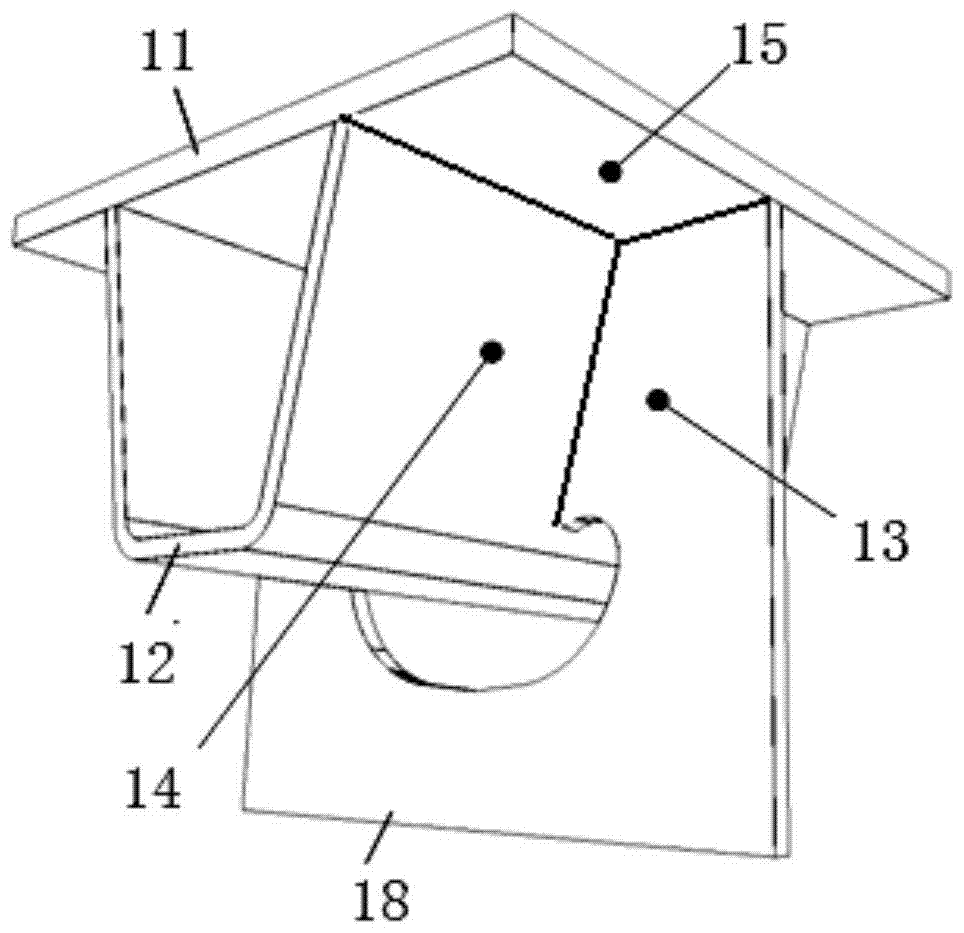
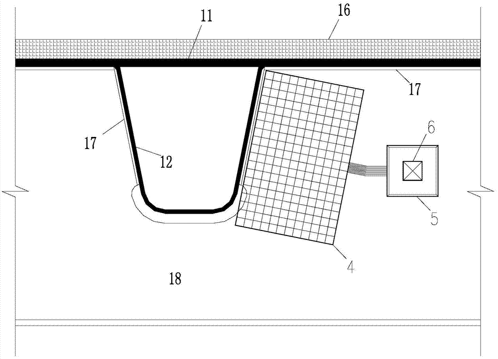
[0037] Such as Figure 1-5 As shown, this embodiment provides a remote monitoring system for fatigue cracks of orthotropic steel bridge decks, including an in-situ detection device 1, a wireless gateway 2 and a remote control device 3, wherein:

[0038] The in-situ detection device 1 is composed of break line components 4, 4-1...4-n, path detectors 5, 5-1...5-n and wireless terminals 6, 6-1...6-n; The breakage line components 4, 4-1...4-n are composed of optical fibers or resistance breakage line...


PUM


Abstract

The invention provides a remote monitoring system and method for fatigue cracks of orthotropic steel bridge decks, including an in-situ detection device composed of a break line assembly, a path detector and a wireless terminal, and a wireless gateway composed of a Zigbee gateway module and a GPRS gateway module And a remote control device composed of a remote server and a remote computer. The break line assembly is composed of two-way orthogonally arranged optical fibers or resistance break lines; the path detector is connected with the break line assembly, and detects each break line according to the instructions of the wireless terminal. The connection or breakage of the components is detected; the Zigbee short-distance wireless transmission network is formed between the Zigbee gateway module and the wireless terminal, and the GPRS long-distance communication is used between the GPRS gateway module and the remote server. The invention realizes the long-term remote monitoring of the fatigue cracks of the orthotropic steel bridge deck, and can be applied in actual engineering.

Description

technical field [0001] The invention relates to the technical field of steel structure monitoring, in particular to a remote monitoring system and method for fatigue cracks of orthotropic steel bridge decks. Background technique [0002] Orthotropic steel bridge decks are widely used in large and medium-span bridge structures due to their light weight, high overall efficiency, strong spanning capacity, and good seismic performance. However, due to the complex structural stress, difficult control of welding defects, and direct bearing of vehicle dynamics, the orthotropic steel bridge deck is also the most prone to fatigue damage in steel bridge structures. Since the first discovery of fatigue cracks in the structural details of steel bridge decks in the British Severn Bridge in 1971, there have been reports of fatigue cracks in steel bridge decks in Germany, France, Japan, the United States, the Netherlands and other countries. my country's Humen Bridge, Haicang Bridge, Jiang...

Claims


Application Information

Patent Timeline
Patent Type & Authority Patents(China)
IPC IPC(8): H04L29/08G01N21/00G01N27/04
Inventor 程斌汤维力
Owner SHANGHAI JIAOTONG UNIV
Learn More