Sliding bearing and centrifugal pump

A technology for sliding bearings and centrifugal pumps, which is applied in the direction of sliding contact bearings, bearings, and bearings for rotating motion, etc., which can solve the problems of high friction power consumption, high vibration and noise of high-speed centrifugal pumps, and low mechanical efficiency, so as to reduce lubricating oil Risk of charring, reduction of vibration and noise levels, effect of improving mechanical efficiency

Active Publication Date: 2014-07-30
WILO CHINA
View PDF7 Cites 7 Cited by
  • Summary
  • Abstract
  • Description
  • Claims
  • Application Information

AI Technical Summary

Problems solved by technology

[0003] The high-speed main shaft of the existing high-speed centrifugal pump is supported by sliding bearings, and the existing sliding bearings are fixed on the bearing housing by fixing devices (such as screws, pins), so there is only a single layer of oil film between the high-speed main shaft and the high-speed main shaft.
[0004] With the increase of speed and radial load, the friction force increases, resulting in large friction power consumption and low mechanical efficiency.
Moreover, since the friction power consumption is all converted into heat, the temperature of the oil film between the high-speed spindle and the sliding bearing rises, resulting in high-temperature carbonization of the lubricating oil, which eventually causes the bearing to fail.
In addition, under the condition of high speed and heavy load, the vibration and noise of the high speed centrifugal pump are very large.

Method used


Image

  • Sliding bearing and centrifugal pump
  • Sliding bearing and centrifugal pump
  • Sliding bearing and centrifugal pump

Examples


Embodiment Construction

[0026] The technical solutions of the present invention will be described in further detail below with reference to the accompanying drawings and embodiments.

[0027] The sliding bearing of the present invention can reduce the friction power consumption between the high-speed main shaft and the bearing of the centrifugal pump, reduce the oil film temperature between the high-speed main shaft and the bearing of the centrifugal pump, improve the reliability of the bearing, thereby improving the reliability of the high-speed centrifugal pump; Vibration and noise levels at high speeds and heavy loads.

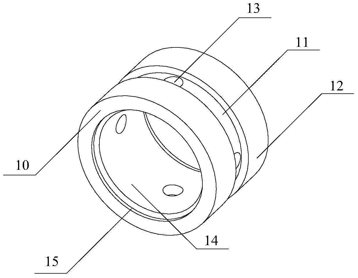
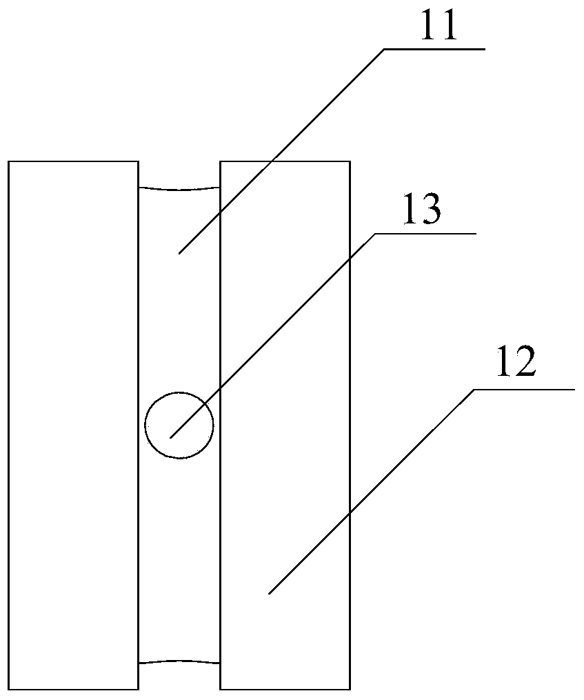
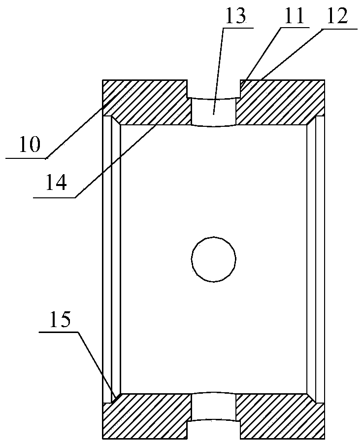
[0028] figure 1 It is a perspective view, a side view and a cross-sectional view of the sliding bearing of the present invention. As shown in the figure, the sliding bearing of the present invention includes a bearing body 10 , an oil groove 11 , a bearing outer ring 12 , an oil hole 13 and a bearing inner ring 14 .

[0029] The oil groove 11 is arranged on the outside of the bea...


PUM


Abstract

The invention relates to a sliding bearing and a centrifugal pump. The sliding bearing comprises an oil groove, a bearing outer ring, an oil hole and a bearing inner ring, wherein the oil groove is annularly formed in the outer side of a bearing body; the bearing outer ring is in sliding fit with an outer bearing block; when the sliding bearing and the bearing block rotate relative to each other, an outer oil film is formed between the bearing outer ring and the bearing block through lubricating oil supplied to the oil groove; the oil hole is formed in the oil groove in a through mode; the bearing inner ring is positioned at the inner side of the bearing body; the bearing inner ring and an outer high-speed spindle are arranged in a sliding mode; when the high-speed spindle and the sliding bearing rotate relative to each other, an inner oil film is formed between the bearing inner ring and the high-speed spindle through the lubricating oil supplied to the oil groove via the oil hole. According to the sliding bearing and the centrifugal pump, because the frictional power consumption between the high-speed spindle and the sliding bearing is reduced, the mechanical efficiency of a high-speed centrifugal pump is improved; the temperature between the high-speed spindle and the sliding bearing is reduced, and the reliability of the high-speed centrifugal pump is improved; transmission of mechanical vibration is reduced due to two oil film dampers, and the vibration and noise level of the high-speed centrifugal pump are reduced.

Description

technical field [0001] The invention relates to a sliding bearing and a centrifugal pump, in particular to a sliding bearing with inner and outer oil films and a high-speed centrifugal pump using the bearing. Background technique [0002] High-speed centrifugal pumps have a wide range of applications and are widely used in petrochemical, pharmaceutical, metallurgy, papermaking, electric power, environmental protection, food and light industry and other industrial fields. [0003] The high-speed main shaft of the existing high-speed centrifugal pump is supported by sliding bearings, and the existing sliding bearings are fixed on the bearing housing by fixing devices (such as screws and pins), so there is only a single layer of oil film between the high-speed main shaft. [0004] With the increase of rotational speed and radial load, the friction force increases, resulting in large friction power consumption and low mechanical efficiency. Moreover, since the friction power co...

Claims


Application Information

Patent Timeline
Patent Type & Authority Applications(China)
IPC IPC(8): F16C17/02F04D29/046
CPCF16C17/18F16C17/02F16C2360/44
Inventor 陈拥军
Owner WILO CHINA
Why Eureka
Try Eureka