Broadband filter adopting one-cavity triple-mode cavity resonator

A resonator and filter technology, applied in waveguide devices, electrical components, circuits, etc., can solve the problem of small tuning range and achieve the effect of simple structure, wide application range and high Q value

Inactive Publication Date: 2014-07-30
SOUTH CHINA UNIV OF TECH
View PDF4 Cites 13 Cited by
  • Summary
  • Abstract
  • Description
  • Claims
  • Application Information

AI Technical Summary

Problems solved by technology

[0007] 4) In January 2004, L.H.Chua et al. published an article titled "Analysis of dielectric loaded cubic cavity for triplemode filter design", proposing to use the coaxial cable as the feed, such as Figure 6a As shown, the dielectric cavity filter structure using tuning screws, the simulation results are as follows Figure 6b As shown; the adjustable range of this structure using coupling screws is relatively small, and there are certain deficiencies

Method used


Image

  • Broadband filter adopting one-cavity triple-mode cavity resonator
  • Broadband filter adopting one-cavity triple-mode cavity resonator
  • Broadband filter adopting one-cavity triple-mode cavity resonator

Examples


Embodiment 1

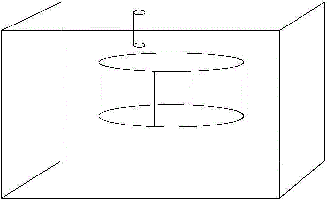
[0049] Such as Figure 7 ~ Figure 10 As shown, the filter of this embodiment includes a cavity 1, a first port 2, a second port 3 and a perturbation metal body 4, the cavity 1 is a rectangular cavity, and the perturbation metal body 4 is in the shape of a cylinder body, the first port 2 and the second port 3 can be used as both input ports and output ports;

[0050] The center of the bottom surface of the perturbation metal body 4 is provided with a fixing / tuning screw 5 integral with the perturbation metal body 4, and the perturbation metal body 4 is connected to the bottom of the cavity 1 through the fixing / tuning screw 5 , the center of the perturbation metal body 4 deviates from the center of the cavity 1; the first port 2 and the second port 3 are respectively arranged on any two mutually perpendicular surfaces of the cavity 1 except the top surface and the bottom surface (in this In the embodiment, the first port 2 is set on the front of the cavity 1, the second port 3 ...

Embodiment 2

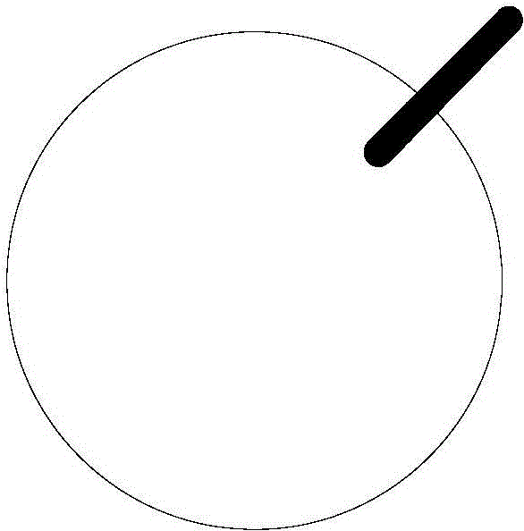
[0056] The main features of this embodiment are: as Figure 16 As shown, the cavity 1 is a cylindrical cavity, and the shape of the perturbation metal body 4 is a cylinder; a rectangular body is also taken during processing, and the bottom is cut, and the bottom of the cut is a closed bottom plate, Dig out a cylindrical cavity in the remaining uncut part, so that this part forms the upper cavity, such as Figure 17 shown. All the other are with embodiment 1.

Embodiment 3

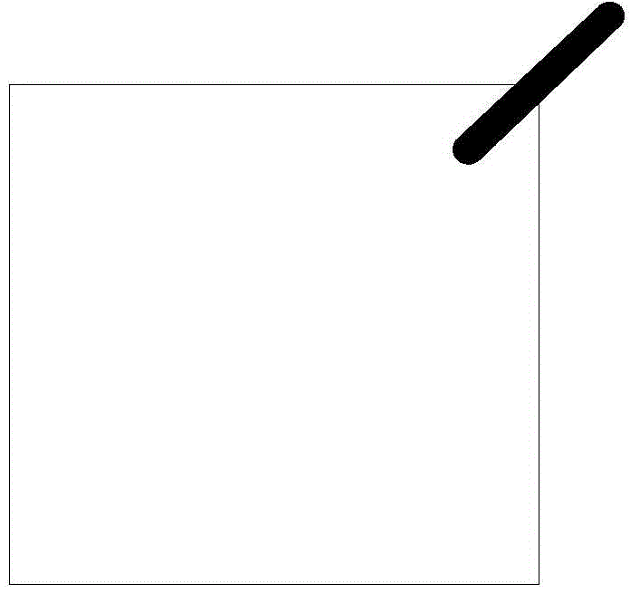
[0058] The main features of this embodiment are: as Figure 18 As shown, the cavity 1 is a cylindrical cavity, and the shape of the perturbation metal body 4 is a rectangle. All the other are with embodiment 1 or 2.


PUM


Abstract

The invention discloses a broadband filter adopting a one-cavity triple-mode cavity resonator. The broadband filter comprises a cavity, a first port, a second port and a perturbation metal body, wherein the perturbation metal body is arranged at the bottom of the cavity, the center of the perturbation metal body deviates from the center of the cavity, and the first port and the second port are arranged on the cavity and penetrate through the outer wall and the inner wall of the cavity. A first conductor assembly is arranged at the first port, a second conductor assembly is arranged at the second port, the axis of the first conductor assembly and the axis of the second conductor assembly are perpendicular to each other and perpendicular to the longitudinal center line of the cavity respectively. A degenerate mode is separated by the method of skewing of the resonator, and therefore, the broadband filter has the advantages of high selectiveness and Q value and simple design, has a wider fractional bandwidth, can meet requirements of miniaturization communication, is easy to manufacture without machining any chamfers or performing slotting, solves the problem of complexity of band wide and narrow machining of the existing cavity filter, and is simple in structure and wide in application range.

Description

technical field [0001] The invention relates to a filter, in particular to a broadband filter using a single-cavity three-mode cavity resonator, and belongs to the field of wireless communication. Background technique [0002] Microwave filter is an indispensable device in the transmitting and receiving ends of modern communication systems. It separates signals, allowing useful signals to pass through without attenuation as much as possible, and suppressing useless signals from passing through with as much attenuation as possible. With the development of wireless communication technology, the frequency band between signals becomes narrower and narrower, which puts forward higher requirements on the specification and reliability of filters. The cavity filter has the advantages of high Q value, large power capacity, easy implementation and stable performance, so it has high application value. The cavity filter achieves inductive or capacitive coupling by opening holes or addi...

Claims


Application Information

Patent Timeline
Patent Type & Authority Applications(China)
IPC IPC(8): H01P1/203
Inventor 王世伟冯世芬林景裕褚庆昕
Owner SOUTH CHINA UNIV OF TECH
Why Eureka
Try Eureka