Flat panel array antenna

An array antenna, flat panel technology, applied in the direction of antenna, antenna array, radiating element structure, etc., can solve the problems of high processing technology requirements, poor loss index, lack of mature flat panel array antenna design technology, etc., to ensure the gain, weight and so on. Lightweight and the effect of reducing microwave transmission loss

Active Publication Date: 2014-07-30
CHENGDU CHUANGXINDA MICROWAVE ELECTRONICS +2
View PDF5 Cites 7 Cited by
  • Summary
  • Abstract
  • Description
  • Claims
  • Application Information

AI Technical Summary

Problems solved by technology

The simulated telecommunications indicators can be very good, but the processing technology requirements are very high, and the actual measured performance indicators seen in the literature, especially the loss indicators are poor
[0004] I...

Method used


Image

  • Flat panel array antenna
  • Flat panel array antenna
  • Flat panel array antenna

Examples


Embodiment Construction

[0026] In order to facilitate those of ordinary skill in the art to better understand the essence of the present invention, the specific implementation manners of the present invention will be described in detail below in conjunction with the accompanying drawings.

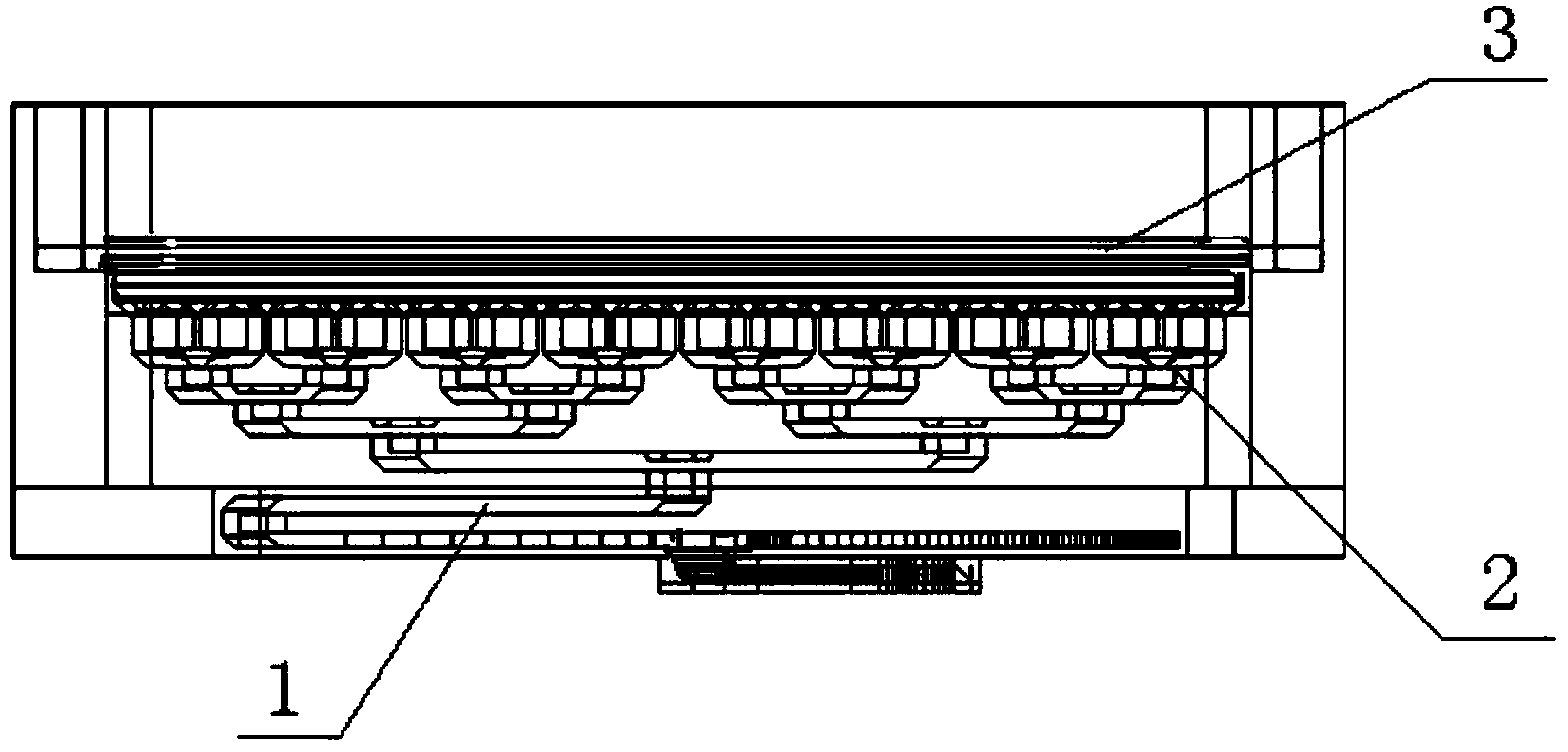
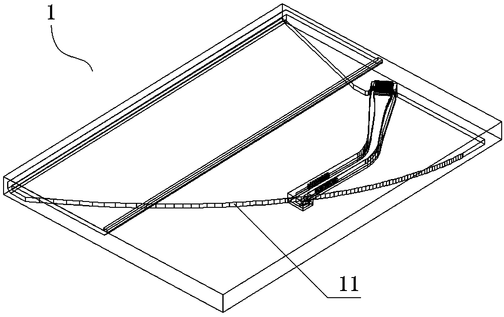
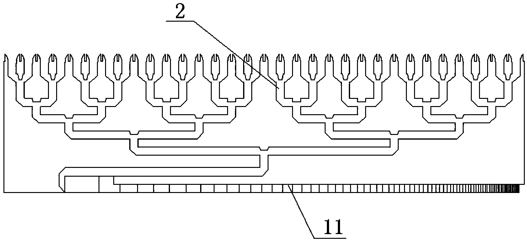
[0027] like figure 1 As shown, a flat panel array antenna is used in the frequency range of 10GHz to 100GHz, and is composed of a flat panel reflector 1, a waveguide power splitter 2 and an antenna radiation unit 3 cascaded. The input port of the panel array antenna adopts WR / 15 standard waveguide (3.16×1.88mm 2 ) feed, the input port is connected to the plate reflector 1 to realize the amplitude distribution of the H surface, the rear end of the plate reflector 1 is connected to the waveguide power divider 2 to realize power distribution, and the terminal of the plate array antenna adopts the antenna radiation unit 3 of a rectangular waveguide plus a dielectric grid . Compared with the existing technology, this...


PUM


Abstract

The invention discloses a flat panel array antenna used for the frequency range of 10 GHz-100 GHz. The flat panel array antenna is characterized by comprising a flat panel reflector, a waveguide power divider and an antenna radiating unit, wherein the waveguide power divider is connected with the output end of the flat panel reflector, and the antenna radiating unit is in signal connection with the waveguide power divider. The flat panel reflector is provided with a multi-point smooth transition reflection side edge, the reflection side edge is located in the face H of the flat panel array antenna and used for performing amplitude weighting distribution on the face H of the flat panel array antenna; the waveguide power divider is connected to one end of the reflection side edge, located in the face E of the flat panel array antenna and used for performing uniform amplitude distribution on the face E of the flat panel array antenna; the antenna radiating unit comprises a rectangular waveguide and a medium grid orthogonally assembled with the rectangular waveguide. Compared with the prior art, the flat panel array antenna has the advantages of being low in loss and good in manufacturability, technical requirements are simple, and the requirement for machining precision is low.

Description

technical field [0001] The present invention relates to an antenna system, in particular to a flat-panel array antenna used in a mobile communication microwave back-haul system and simultaneously used for wireless WIFI point-to-point (point-point link) signal transmission between base stations. Background technique [0002] An antenna is a transformer that transforms a guided wave propagating on a transmission line into an electromagnetic wave propagating in an unbounded medium, or vice versa. A component used in radio equipment to transmit or receive electromagnetic waves. Engineering systems such as radio communication, broadcasting, television, radar, navigation, electronic countermeasures, remote sensing, and radio astronomy, which use electromagnetic waves to transmit information, rely on antennas to work. [0003] At present, the commonly used antennas in the world mainly include the following schemes. 1) The microstrip line scheme is characterized by simple processin...

Claims


Application Information

Patent Timeline
IPC IPC(8): H01Q21/00H01Q19/10H01Q15/14H01Q1/36H01P5/12
CPCH01Q21/00
Inventor 陈志兴杨华云宇杨坚
Owner CHENGDU CHUANGXINDA MICROWAVE ELECTRONICS
Why Eureka
Try Eureka