Inverter

A technology of inverter and switching unit, which is applied in the direction of converting AC power input to DC power output, output power conversion device, electrical components, etc., and can solve the problem of increased electromagnetic interference, large inrush current, breakdown of switching devices, etc. problem, achieve the effect of reducing electromagnetic interference, improving life, reducing volume and weight

Active Publication Date: 2014-07-30
HUAWEI DIGITAL POWER TECH CO LTD
View PDF5 Cites 5 Cited by
  • Summary
  • Abstract
  • Description
  • Claims
  • Application Information

AI Technical Summary

Problems solved by technology

The higher the frequency of the switching device, the larger the current peak, which is easy to cause overheating damage to the switching device
In addition, since there is a reverse recovery period when the diode connected in parallel with the switching device turns from on to off, if the switching device is turned on and operated during the reverse recovery period of the diode, it is easy to generate a large inrush current, and the switching frequency of the switching device is higher. High, the greater the inrush current, it will cause harm to the safe operation of the switching device
In addition, when the switching device is turned off, the inductance and other inductive elements in the circuit will induce spikes. The higher the switching frequency of the switching device, the faster the turn-off, the greater the voltage value of the spike on the inductive element. When the voltage The peak pulse with high value is loaded on both ends of the switching device, which is easy to cause the breakdown of the switching device
In addition, as the switching frequency of the switching device increases, the electromagnetic interference increases, which affects the work of other components in the inverter and electronic equipment around the inverter.

Method used


Image

  • Inverter
  • Inverter
  • Inverter

Examples


Embodiment Construction

[0030] The following will clearly and completely describe the technical solutions in the embodiments of the present invention with reference to the accompanying drawings in the embodiments of the present invention. Obviously, the described embodiments are only some of the embodiments of the present invention, not all of them. Based on the embodiments of the present invention, all other embodiments obtained by persons of ordinary skill in the art without making creative efforts belong to the protection scope of the present invention.

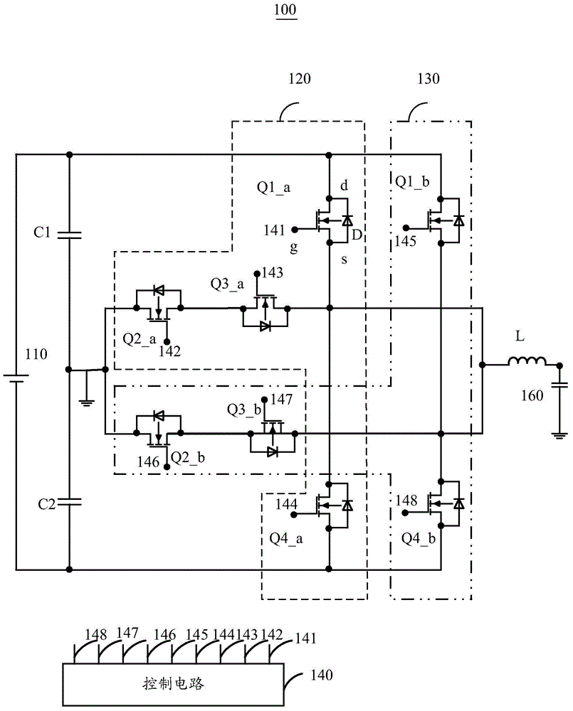
[0031] see figure 1 , which is a circuit diagram of an inverter in a preferred embodiment of the present invention. The inverter 100 is used to convert a DC power into an AC power. The inverter 100 includes a DC power source 110 , a first switch module 120 , a second switch module 130 , an inductor L and a control circuit 140 . The DC power supply 110 is used to generate the DC power and output the DC power. The first switch module 120 and the...


PUM


Abstract

The invention provides an inverter used for converting DC to AC. The inverter comprises a DC power supply, a first switching module, a second switching module, an inductor and a control circuit. The DC power supply produces the DC, the first switching module and the second switching module are used for receiving the DC, and the first switching module and the second switching module are connected in parallel. One parallel end of the first switching module and one parallel end of the second switching module are grounded in a point mode. The other parallel end of the first switching module and the other parallel end of the second switching module are in point connection with one end of the inductor. The other end of the inductor is used for outputting the AC. The control circuit emits a sine pulse width modulation signal serving as a control signal to control the first switching module and the second switching module to alternately output voltage to the inductor. The inductor is used for converting the DC to the AC in cooperation with the first switching module and the second switching module. According to the inverter, the size and the weight of the inverter can be effectively reduced, electromagnetic interference is reduced, and therefore the inverter has long service life.

Description

technical field [0001] The invention relates to the field of electric energy conversion, in particular to an inverter. Background technique [0002] An inverter is a device that converts DC voltage into AC voltage and plays an important role in electronic circuits. Inverters usually include switching devices, inductors, and capacitors. The high frequency switching frequency of switching devices is an important symbol of the technical content of power electronic products. Increasing the switching frequency of the switching devices can reduce the volume and weight of the inverter. However, increasing the switching frequency of the switching device will increase the turn-on loss and turn-off loss of the switching device. Further, when the switching device is turned on, the energy stored in the junction capacitance of the switching device is dissipated in the switching device in the form of current. The higher the frequency of the switching device, the larger the peak of the...

Claims


Application Information

Patent Timeline
Patent Type & Authority Applications(China)
IPC IPC(8): H02M7/527
Inventor 石勇
Owner HUAWEI DIGITAL POWER TECH CO LTD
Why Eureka
Try Eureka