Electric field type time-grating angular displacement sensor

一种位移传感器、栅角的技术,应用在转换传感器输出、仪器、采用电装置等方向,能够解决不一致、电场耦合强度不一致、信号相互干扰电极长宽比等问题,达到功耗低、机械安装精度要求低、结构简单的效果

Active Publication Date: 2014-08-06
CHONGQING TIMSENS PRECISION EQUIP TECH CO LTD
View PDF7 Cites 45 Cited by
  • Summary
  • Abstract
  • Description
  • Claims
  • Application Information

AI Technical Summary

Problems solved by technology

[0004] The purpose of the present invention is to address the deficiencies of the above-mentioned prior art, and propose an electric field type time grating angular displacement sensor based on a single-turn multilayer structure, which uses electrodes based on a single-turn multilayer structure to solve the signal interaction between the two turns. Interference and inconsistency of electrode aspect ratio, avoiding the inconsistency of the two-circle electric field coupling strength caused by processing and installation; using the electric field coupling principle to directly obtain the traveling wave signal, without the need for an adding circuit; thus reducing measurement errors and reducing the impact on installation accuracy requirements, simplify the system structure

Method used


Image

  • Electric field type time-grating angular displacement sensor
  • Electric field type time-grating angular displacement sensor
  • Electric field type time-grating angular displacement sensor

Examples


Embodiment Construction

[0021] The present invention will be further described below in conjunction with accompanying drawing.

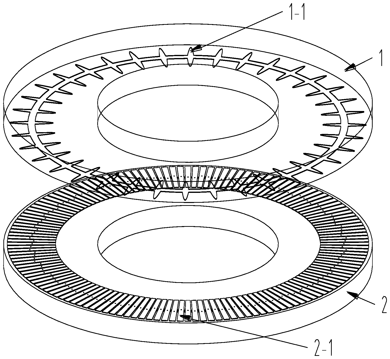
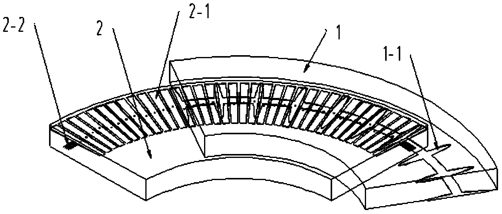
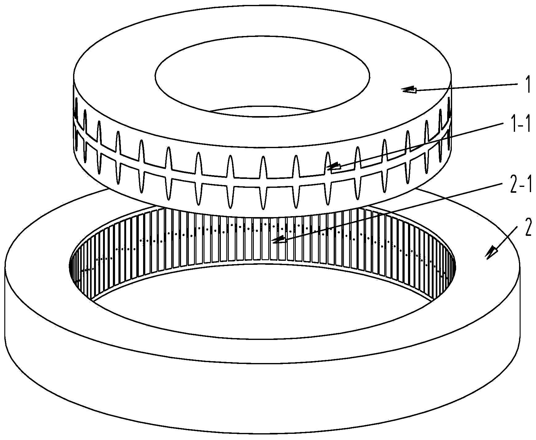
[0022] Figure 1(a), Figure 1(b), Figure 2(a), Figure 2(b) and image 3 As shown, the sensor of the present invention includes two parts, the rotor base 1 and the stator base 2; ceramics are used as the base material, and a layer of iron-nickel alloy is sprayed on the surface of the ceramics as electrodes. There are two implementation modes.

[0023] Structural form 1, Fig. 1(a) and Fig. 1(b): On the lower end surface of the cylinder of the rotor base 1, a circle of rotor electrodes 1-1 of the same size and shape are equally spaced along the circumferential direction, a total of 36, the rotor After the electrodes are deployed along the circumferential direction, the shape is a double sinusoidal shape formed by two sinusoidal symmetry up and down. The lead wires with a width of 1.8mm connect each rotor electrode. On the two circumferences of , the central angle corresponding ...


PUM


Abstract

The invention discloses an electric field type time-grating angular displacement sensor. The electric field type time-grating angular displacement sensor comprises a rotor and a stator, wherein the surface of a base body of the rotor is covered with a circle of dual-sinusoid electrodes which are arranged at equal intervals, the surface of the base body of the stator is evenly covered with a circle of fan-ring-shaped or curved-surface rectangular electrodes, a stator lead are arranged on the bottoms of the electrodes, an insulating layer is arranged between the electrodes and the lead, the surfaces of the electrodes are covered with an insulating protective layer, and thus a multi-layer structure is formed; the base body of the rotor and the base body of the stator are installed coaxially, and a certain gap delta is reserved between the base body of the rotor and the base body of the stator; the base body of the rotor rotates relatively around the axis; the four electrodes in a cycle of the stator are connected with a sinusoidal excitation voltage with a phase of 0 degree, a sinusoidal excitation voltage with a phase of 90 degrees, a sinusoidal excitation voltage with a phase of 180 degrees and a sinusoidal excitation voltage with a phase of 270 degree respectively, the amplitudes and the frequencies of the sinusoidal excitation voltages are equal, and the phases of traveling wave signals Uo generated by the electrodes of the rotor are compared with the phases of a path of fixed-phase reference signals Ur with the same frequency; the phase difference between the two paths of signals is represented by interpolated clock pulses, and an angular displacement value is obtained through conversion. The electric field type time-grating angular displacement sensor is simple in structure and low in power consumption, requirements for mechanical installation precision are low, and free high-precision angle displacement measurement within the range of 360 degrees can be achieved.

Description

technical field [0001] The invention belongs to a precision angular displacement measuring sensor. Background technique [0002] In the field of precision angular displacement measurement, a time grating sensor with clock pulse as the reference for displacement measurement has been developed in recent years, and a time grating angular displacement sensor based on alternating electric field has been developed on this basis. This sensor patent was published on April 25, 2012. Patent name: A time grating angular displacement sensor based on alternating electric field. Patent document number: CN102425987A. [0003] This time grating angular displacement sensor based on an alternating electric field uses a single-layer differential capacitor as a signal coupling channel, and requires two rings of electrodes to form two standing wave signals, and then synthesizes a traveling wave signal by an adding circuit. Since the length-to-width ratios of the two rings of electrodes processe...

Claims


Application Information

Patent Timeline
Patent Type & Authority Applications(China)
IPC IPC(8): G01B7/30
CPCG01D5/241G01D5/243G01B7/30
Inventor 刘小康黄沛彭东林周启武蒲红吉
Owner CHONGQING TIMSENS PRECISION EQUIP TECH CO LTD
Why Eureka
Try Eureka