Device and method for measuring micro impulse by means of linear frequency modulation multi-beam laser heterodyne quadratic harmonic method and torsional pendulum method

A linear frequency modulation, laser heterodyne technology, applied in the field of optics, can solve the problems of small impulse, large accidental error, low measurement accuracy, etc.

Inactive Publication Date: 2014-08-06
HEILONGJIANG UNIV
View PDF11 Cites 5 Cited by
  • Summary
  • Abstract
  • Description
  • Claims
  • Application Information

AI Technical Summary

Problems solved by technology

[0004] In order to solve the problems that the existing laser interferometry has large accidental errors and low measurement accuracy in measuring micro-pulses, the present in

Method used


Image

  • Device and method for measuring micro impulse by means of linear frequency modulation multi-beam laser heterodyne quadratic harmonic method and torsional pendulum method
  • Device and method for measuring micro impulse by means of linear frequency modulation multi-beam laser heterodyne quadratic harmonic method and torsional pendulum method
  • Device and method for measuring micro impulse by means of linear frequency modulation multi-beam laser heterodyne quadratic harmonic method and torsional pendulum method

Examples


specific Embodiment approach 2

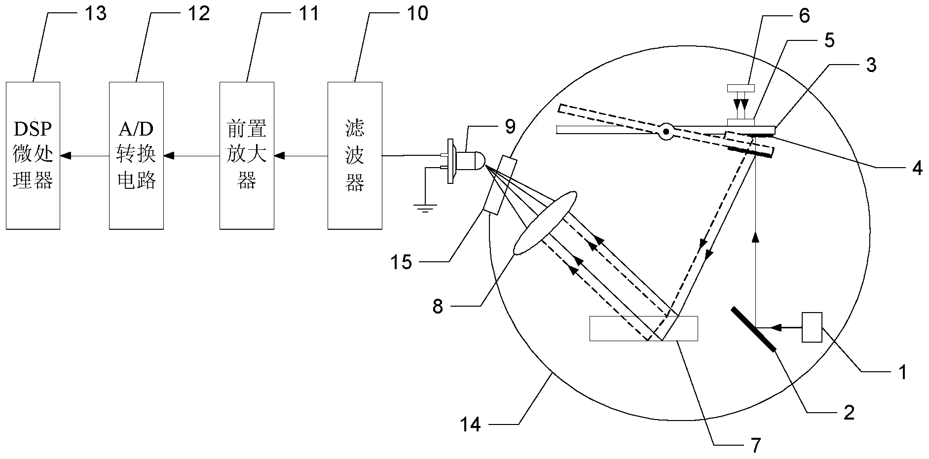
[0034] Specific implementation mode two: the following combination figure 2 Describe this embodiment, this embodiment will further explain the device for measuring the micro-pulse by using the chirp multi-beam laser heterodyne second harmonic method and the torsion method described in the first embodiment. The signal processing system includes a filter 10, a front Amplifier 11, A / D conversion circuit 12 and DSP microprocessor 13;

[0035]The input end of the filter 10 is connected to the electrical signal output end of the photodetector 9; the output end of the filter 10 is connected to the input end of the preamplifier 11; the output end of the preamplifier circuit 11 is connected to the analog signal of the A / D conversion circuit 12 The input end; the digital signal output end of the A / D conversion circuit 12 is connected to the input end of the DSP microprocessor 13 .

specific Embodiment approach 3

[0036] Specific implementation mode three: refer to figure 2 Describe this embodiment in detail, according to the method for measuring the micro-pulse with the device for measuring the micro-pulse by using the chirp multi-beam laser heterodyne second harmonic method and the torsion method described in the second specific embodiment, the method includes the following steps:

[0037] Step 1, turn on chirp laser 1 and pulse laser 6 at the same time;

[0038] Using the pulsed laser 6 to emit pulsed laser light to excite the working medium target 5, so that the working medium target 5 generates plasma spray, and the backspray effect of the plasma spray produced by the working medium target 5 causes the standard beam 3 to rotate;

[0039] Step 2: The signal processing system continuously collects the electrical signals sent by the photodetector 9 during the swinging process of the torsion system, and processes the continuously obtained electrical signals, and measures the beam inci...

specific Embodiment approach 4

[0045] Embodiment 4: This embodiment is a further description of the method for measuring micro-pulse by using the chirp multi-beam laser heterodyne second harmonic method and the torsion method described in the third embodiment. In step 2, the chirp multi-beam is used The laser heterodyne second harmonic method measures the incident angle θ of the beam incident on the plane standard mirror 7 0 The method of obtaining:

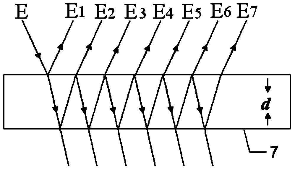
[0046] Step 21, the total light field E of the light beam of photodetector 9 Σ (t):

[0047] E. Σ (t)=E 1 (t)+E 2 (t)+...+E m (t);

[0048] Among them: E 1 (t) is the reflected light field after the light beam is reflected by the front surface of the plane standard mirror 7, and according to the formula

[0049] E 1 ( t ) = α 1 E 0 exp { i [ ...


PUM

PropertyMeasurementUnit
Thicknessaaaaaaaaaa
Wavelengthaaaaaaaaaa

Abstract

The invention provides a device and method for measuring micro impulse by means of a linear frequency modulation multi-beam laser heterodyne quadratic harmonic method and a torsional pendulum method, and belongs to the field of optics. The device and method are aimed to solve the problems that according to an existing laser interference method for measuring the micro impulse, accidental errors are large and measurement precision is low. Linearly polarized light emitted from a linear frequency modulation laser device is reflected through a first plane reflection mirror and a second plane reflection mirror and then enters a plane standard lens, light beams penetrating through the front surface of the plane standard lens are reflected by the rear surface and the front surface of the plane standard lens in the plane standard mirror for many times, then multiple beams of reflection light are obtained, the beams of reflection light penetrate through the front surface of the plane standard lens, then the beams of the reflection light and the light beams reflected through the front surface of the plane standard lens penetrate through a vacuum window and are converged to a photosensitive face of a photoelectric detector outside a vacuum chamber through a convergence lens, the photoelectric detector outputs electric signals to a signal processing system, and the signal processing system obtains the micro impulse borne by a standard beam according to the electric signals received continuously. The device and method are suitable for measuring the micro impulse.

Description

technical field [0001] The present invention belongs to the field of optics. Background technique [0002] Laser micro-thrusters have broad and in-depth application prospects in the field of attitude and orbit control of micro-satellites. Significant advantages such as digital control have attracted extensive attention from scholars at home and abroad. The impulse is an important parameter reflecting the performance of the laser micro thruster, which is characterized by a small magnitude, about 10 -7 ~10 -5 N·s. In 1999, Phipps et al. from the Photonic Associates group proposed to use the torsion pendulum system to measure the micro-impulse generated by the laser micro-thruster, and used it to test the performance parameters of the micro-thruster; in 2002, Phipps et al. improved the torsion system, and then The domestic University of Science and Technology of China and the Institute of Equipment Command Technology have also carried out related research. Judging from the...

Claims


Application Information

Patent Timeline
IPC IPC(8): G01L5/00
Inventor 李彦超周巍刘明亮杨九如冉玲苓高扬杨瑞海杜军丁群王春晖马立峰于伟波
Owner HEILONGJIANG UNIV
Why Eureka
Try Eureka