A circular seam welding device and a circular seam welding method for aircraft pipeline parts

A technology for circumferential seam welding and aircraft pipe, applied in the field of welding processing, can solve the problems of single use function, increased difficulty in tooling management, long production cycle, etc., and achieves the effects of complete functions, light weight and high welding efficiency

Inactive Publication Date: 2016-03-16
NORTHWESTERN POLYTECHNICAL UNIV
View PDF8 Cites 2 Cited by
  • Summary
  • Abstract
  • Description
  • Claims
  • Application Information

AI Technical Summary

Problems solved by technology

[0005] In order to overcome the problems of long production cycle of welding fixtures in the prior art, single use function, increased difficulty of tooling management, and special welding fixtures can only perform girth welding of two-part circular pipes with specific inner diameters, the present invention proposes an aircraft pipeline The circular seam welding device and the circular seam welding method of the parts, according to the difference in the inner diameter of the round pipe to be welded, adjust the inner support unit in the welding device, so that the inner diameter of the pipe to be welded can be changed flexibly within a certain range, and two Accurate splicing and clamping of some pipe fittings to be welded, and then perform circumferential seam welding; according to requirements, shielding gas can be connected to the welding seam area to complete circumferential seam welding that requires gas shielding materials

Method used


Image

  • A circular seam welding device and a circular seam welding method for aircraft pipeline parts
  • A circular seam welding device and a circular seam welding method for aircraft pipeline parts
  • A circular seam welding device and a circular seam welding method for aircraft pipeline parts

Examples


Embodiment Construction

[0029] This embodiment is a circular seam welding device and a circular seam welding method for aircraft pipeline parts.

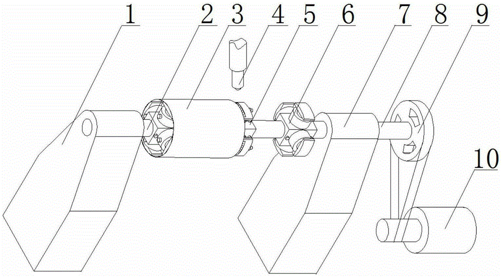
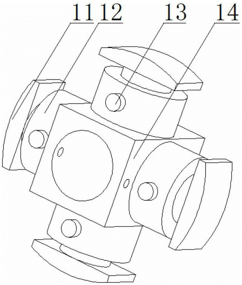
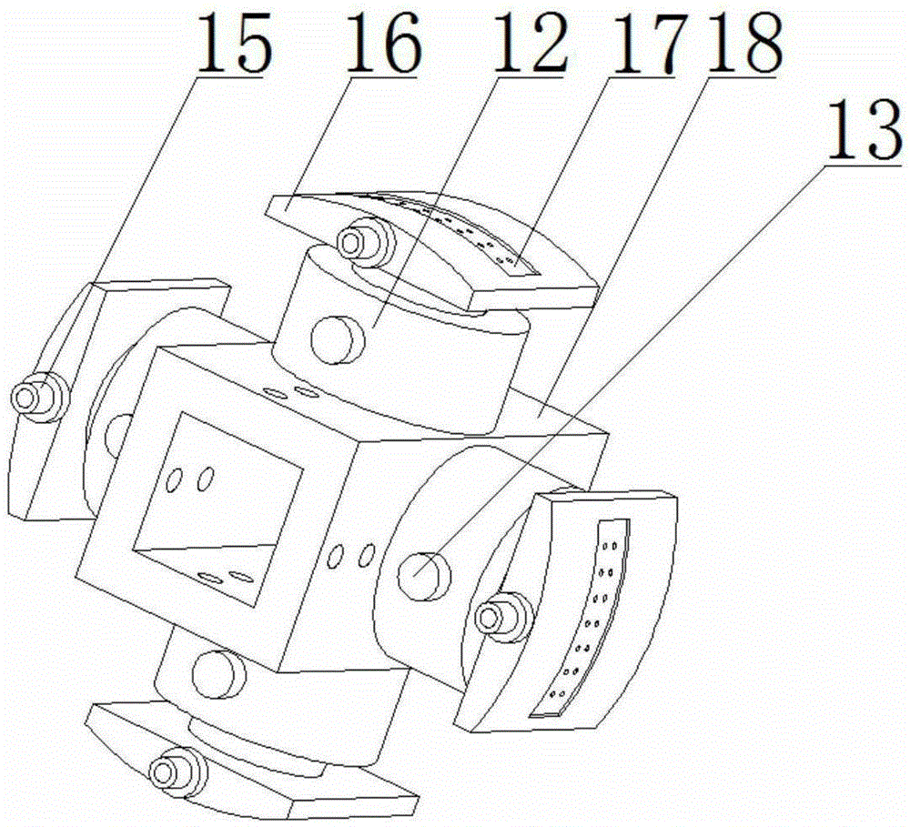
[0030] refer to Figure 1 to Figure 9, the circumferential seam welding device for pipeline parts in this embodiment includes a first base 7, a second base 1, a first main shaft 8, a second main shaft 2, a first inner support unit 5, a second inner support unit 6, and a pulley 9. Power unit 10, welding robot arm 4, synchronous hydraulic pump console 20, the first base 7 is fixedly installed between the power unit 10 and the second base 1, and the first main shaft 8 is installed on the first base 7 The end of the cylindrical section of the first main shaft 8 is equipped with a pulley 9, and is installed on the same side of the first base 7 as the power unit 10, and the first inner support unit 5 is installed at the end of the square section of the first main shaft 8, the first The inner support unit 5 is located in the weld seam area of ​​the pipe piece 3 ...


PUM


Abstract

The invention discloses a girth welding device and a girth welding method for an aircraft pipeline component. The welding device consists of bases, main shafts, inner support units, a welding robot and power units, wherein the first base is fixed; the first main shaft is mounted on the first base; the second main shaft is mounted on the second base and is moved along with the axial sliding of the second base; the inner support units are respectively mounted on the two main shafts; hydraulic pumps are respectively positioned between each sliding block and each arc-shaped block; the first inner support units are positioned in a welding seam area; the two second inner support units are respectively mounted at the non-welding ends of pipelines to achieve a supporting effect. The inner support units in the welding device are adjusted according to different inside diameter sizes of circular pipes to be welded, so that the inside diameters of the pipes to be welded can change flexibly within a certain range; the two parts of the pipes to be welded are spliced and clamped accurately; the welding robot is mounted in the welding seam area to perform girth welding on the pipes. The power units provide rotating power for the overall girth welding device.

Description

technical field [0001] The invention belongs to the technical field of welding processing, and in particular relates to a circular seam welding device and a circular seam welding method for aircraft pipeline parts. Background technique [0002] With the rapid development of modern industrial production, the number of pipe fittings in various products is increasing; especially in the aviation manufacturing industry, there are a large number of oil and gas pipeline parts in the processing of aircraft parts. Among them, welding is the most commonly used and the most numerous processing method. The welding device is the process equipment for positioning and fastening the welding parts for welding. The characteristics of the welding fixture are determined by the assembly welding process and the form of the welding structure. At present, welding fixtures generally design a set of special fixtures for one welding station. If the workpiece changes, a new set of special welding fixt...

Claims


Application Information

Patent Timeline
Patent Type & Authority Patents(China)
IPC IPC(8): B23K37/053B23K37/00
CPCB23K37/0531B23K37/0538
Inventor 孙宝龙王永军杨凯郝耀武
Owner NORTHWESTERN POLYTECHNICAL UNIV
Why Eureka
Try Eureka