Purification device and separation method of oily sewage

A sewage purification and purification device technology, which is applied in the direction of separation method, liquid separation, grease/oily substance/floating matter removal device, etc., can solve the problems of separation method limitation and achieve the effect of low flow rate

Active Publication Date: 2014-08-13
CHINA UNIV OF MINING & TECH
View PDF3 Cites 7 Cited by
  • Summary
  • Abstract
  • Description
  • Claims
  • Application Information

AI Technical Summary

Problems solved by technology

[0004] The purpose of the present invention is to provide an oily sewage purification device and separation method for separating fine-grained emulsified oil and high separation efficiency, so as to solve the problem that the existing separation methods are limited in practical application due to economic or technological inventions

Method used


Image

  • Purification device and separation method of oily sewage
  • Purification device and separation method of oily sewage
  • Purification device and separation method of oily sewage

Examples


Embodiment 1

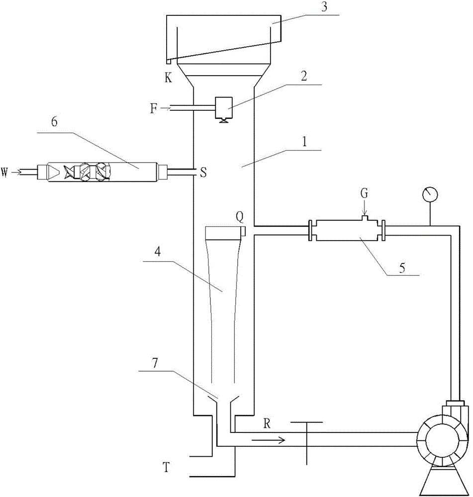
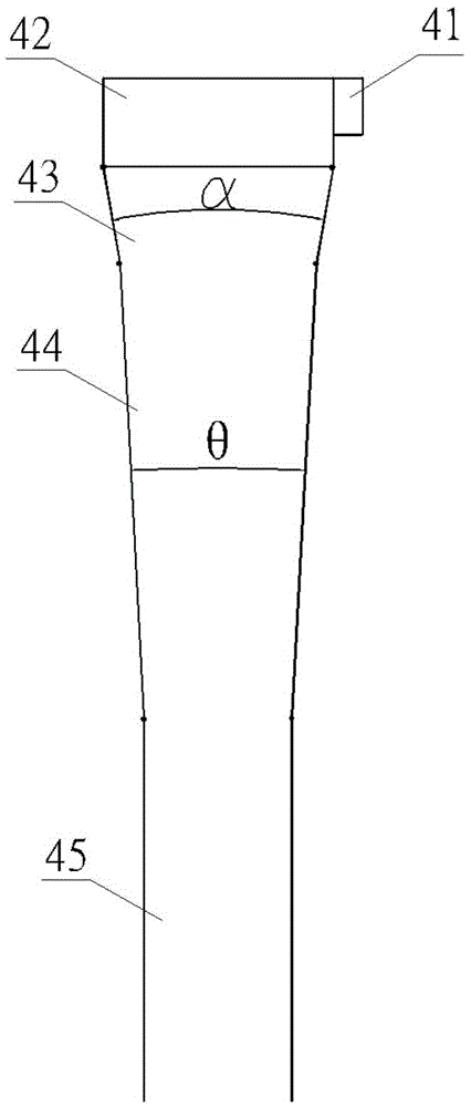
[0020] Embodiment 1: The purification device includes a column separator 1, an inflow distribution device 2, a floating oil collection device 3, at least one inflatable cyclone separator 4, at least one self-priming microbubble generator 5 and at least one dissolved air separation microbubble generator. Bubble generator 6; in the column body of described purifying device, the upper part is column separator 1, and the lower part is inflatable cyclone separator 4; The filling point Q of the formula microbubble generator 5 is at the lower part of the cylinder.

[0021] The water inlet distribution device 2 is connected to the feeding pipe at the upper center of the column separator 1 .

[0022] One section of the self-priming microbubble generator 5 is connected to a circulating pump through a pipeline, and one section enters the column separator 1 through a pipeline and is connected to the tangential inlet Q of the inflatable cyclone.

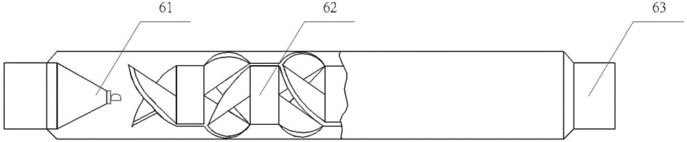
[0023] Described gas-dissolved micro-bubb...

Embodiment 2

[0028] Example 2: In figure 1 Among them, along the column separator 1 from top to bottom, there are water inlet distribution device 2, gas filling point S of dissolved air precipitation microbubble generator 6, gas filling point Q of self-priming microbubble generator and gas cyclone separator 4 . The water inlet is at the middle and upper part of the cylinder, and is connected with the water inlet distribution device. The dissolved air precipitation microbubble generator 6 is placed outside the column, and a tube is connected with the dissolved air precipitation microbubble generator 6 and inserted into the column body, and the insertion position is in the middle of the column body. Further down is the gas-filled cyclone separator 4, and the lower segment of the gas-charged cyclone is an inverted cone 7. The self-priming microbubble generator 5 is placed outside the column, one section of which is connected to the outlet of the circulation pump through a pipeline, and the ...


PUM

PropertyMeasurementUnit
particle diameteraaaaaaaaaa

Abstract

The invention discloses a purification device and a separation method of oily sewage. The device comprises a water inlet allocation device, a column separator, a floating oil collection device, an inflatable cyclone separator, at least one self-sucked type micro-bubble generator and at least one dissolved gas separation micro-bubble generator, wherein the column separator is arranged at the upper part of the column body; the built-in inflatable cyclone separator is arranged at the lower part of the column body; the column separator and the inflatable cyclone separator are communicated vertically; an inflation point of the dissolved gas separation micro-bubble generator is arranged at the upper part of the column body; an inflation point of the self-sucked type micro-bubble generator is arranged at the lower part of the column body. By adopting the two inflation modes that the micro-bubble is generated through negative self-sucked ejection air flow and high-pressure dissolved gas depressurization separation, the hydrocyclone separation and the floating separation are coupled, refined granular oil in the oily sewage can be effectively separated, the low limit of effective flotation granularity is small, the separation time is short, the operation cost is low, and the problem that emulsified oil in the oily sewage is hard to separate is solved.

Description

technical field [0001] The invention relates to an oil-water separation and purification device and a separation method, in particular to a purification device and a separation method for oily sewage containing emulsified oil. technical background [0002] Oily sewage is a wide-ranging and large-scale pollution source produced in petroleum development and utilization activities. Effective treatment of oily sewage, discharge of sewage up to standard, and recovery of oil products not only protect the environment, but also generate economic benefits, realizing the unity of environmental and economic benefits. [0003] The oil in oily sewage mainly exists in the water body in the form of slick oil, dispersed oil, emulsified oil, dissolved oil and oil-solid matter. The difficulty of oil-water separation depends on the form of oil in the water. The finely dispersed oil and emulsified oil in the colloidal state in the sewage have a small particle size, and often adhere to some imp...

Claims


Application Information

Patent Timeline
Patent Type & Authority Applications(China)
IPC IPC(8): C02F1/40C02F1/24C02F1/38
Inventor 李小兵刘炯天厉伟赵昌海
Owner CHINA UNIV OF MINING & TECH
Why Eureka
Try Eureka