Arc striking device for plasma coating equipment

A technology of coating equipment and arc striking device, which is applied in the field of power supply, can solve the problems of high cost, fast rectifier interference, and heavy weight, and achieve the effect of simple device, high reliability, and light weight

Active Publication Date: 2016-04-27
GAOYOU INST CO LTD DALIAN UNIV OF TECH
View PDF8 Cites 0 Cited by
  • Summary
  • Abstract
  • Description
  • Claims
  • Application Information

AI Technical Summary

Problems solved by technology

[0006] (1) The spark arrester of the high-frequency arc starter is easy to ablate, and the gap is difficult to adjust;
[0007] (2) Large in size and heavy in quality;
[0008] (3) The high-frequency arc starter seriously interferes with computers, communications, fast switching tubes and fast rectifier tubes
[0009] However, the power frequency step-up pulse arc starter is bulky and expensive

Method used


Image

  • Arc striking device for plasma coating equipment

Examples


Embodiment

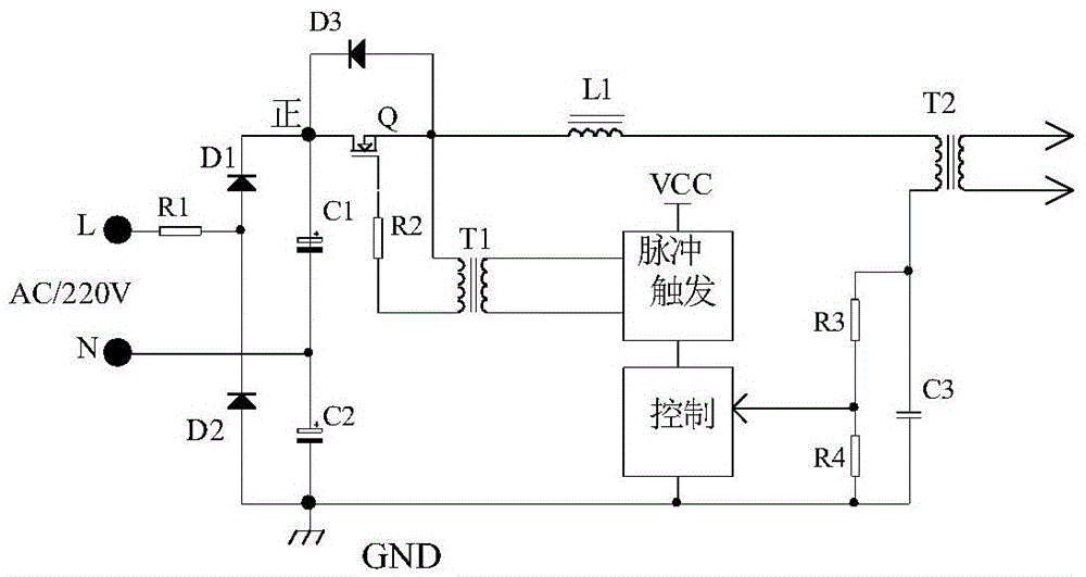
[0018] Such as figure 1 An arc striking device for plasma coating equipment is shown, in which diodes D1 and D2, electrolytic capacitors C1 and C2 form a voltage doubler rectifier, and the voltage at both ends of C1 and C2 connected in series is 2*1.414 times the input AC voltage, that is, 220V *2.828 up to 622V, the connection method is that diodes D1 and D2 are connected in series in the same direction, and electrolytic capacitors C1 and C2 are also connected in series in the same direction. The L and N connections of the mains AC are respectively connected to the series connection point of diodes D1 and D2 and the electrolytic capacitors C1 and C2 in series The connection point, the negative terminal and the positive terminal of the series-connected diodes D1 and D2 are respectively connected to the positive and negative terminals of the series-connected electrolytic capacitors C1 and C2, and the connection point of the diode D1 and the electrolytic capacitor C1 is connected...


PUM


Abstract

The invention relates to an arc initiation device for plasma coating equipment. The arc initiation device is respectively connected with a series connection point of diodes D1 and D2 and a series connection point of electrolysis capacitors C1 and C2 through current-limiting resistors R1 and N via L of a commercial power AC (Alternating Current); a connecting point of the diode D1 and the electrolysis capacitor C1 is connected with a drain electrode of an MOS (Metal Oxide Semiconductor) tube Q; the MOS tube Q is inversely connected with a diode D3 in parallel; a control electrode of the MOS tube Q is connected with one end of the secondary terminal of a trigger transformer T1 through a resistor R2; a source electrode of the MOS tube Q is connected with the other end of the secondary terminal of the trigger transformer T1; a capacitor C3 is in spanned connection to two ends of a resistor R3 and a resistor R4; an input terminal of the trigger transformer T1 is connected with a pulse trigger circuit; the pulse trigger circuit is connected with a control circuit and a connecting point of the resistor R4 and the resistor R3. According to the arc initiation device, a huge and expensive power frequency boosting transformer is replaced with double voltage rectification; a pulse arc initiation voltage is output by a pulse-boosting isolation transformer via a pulse triggering crystal switch technology. Thus, the arc initiation device provided by the invention has the advantages of stability, safety and reliability.

Description

technical field [0001] The invention belongs to the field of power supplies, in particular to an arc striking device. Background technique [0002] The principle of arc coating and arc ion plating is based on the theory of cold cathode self-sustaining vacuum arc discharge. In the arc source ion plating, the coating material is used as the target (cathode), and arc discharge is generated on the target surface by means of an arc-leading device. Using low voltage, high current, and arc discharge technology, gas discharge or partial ionization of evaporated substances is used, and the evaporated substances or their reaction products are deposited on the substrate under the bombardment of gas ions or evaporated substance ions. It is a self-evaporating and self-ionizing solid evaporation source. This evaporation source can evaporate metal materials and alloy materials, and can also perform reactive ion plating, such as TiN, TiC, (TiAl)N, ZrN, and other superhard films, Al, Ag, C...

Claims


Application Information

Patent Timeline
Patent Type & Authority Patents(China)
IPC IPC(8): C23C14/32
Inventor 林国强钱立平韩治昀魏科科
Owner GAOYOU INST CO LTD DALIAN UNIV OF TECH
Why Eureka
Try Eureka