Flexible supporting device and flexible supporting pieces of photoetching machine

A technology of flexible support and lithography machine, which is applied in photoplate-making process exposure devices, microlithography exposure equipment, non-rotational vibration suppression, etc. question

Active Publication Date: 2014-08-13
SHANGHAI MICRO ELECTRONICS EQUIP (GRP) CO LTD
View PDF7 Cites 9 Cited by
  • Summary
  • Abstract
  • Description
  • Claims
  • Application Information

AI Technical Summary

Problems solved by technology

[0010] The technical problem to be solved by the present invention is that the flexible support cannot take into account both good support force and ultra-low rigidity,

Method used


Image

  • Flexible supporting device and flexible supporting pieces of photoetching machine
  • Flexible supporting device and flexible supporting pieces of photoetching machine
  • Flexible supporting device and flexible supporting pieces of photoetching machine

Examples


Embodiment 1

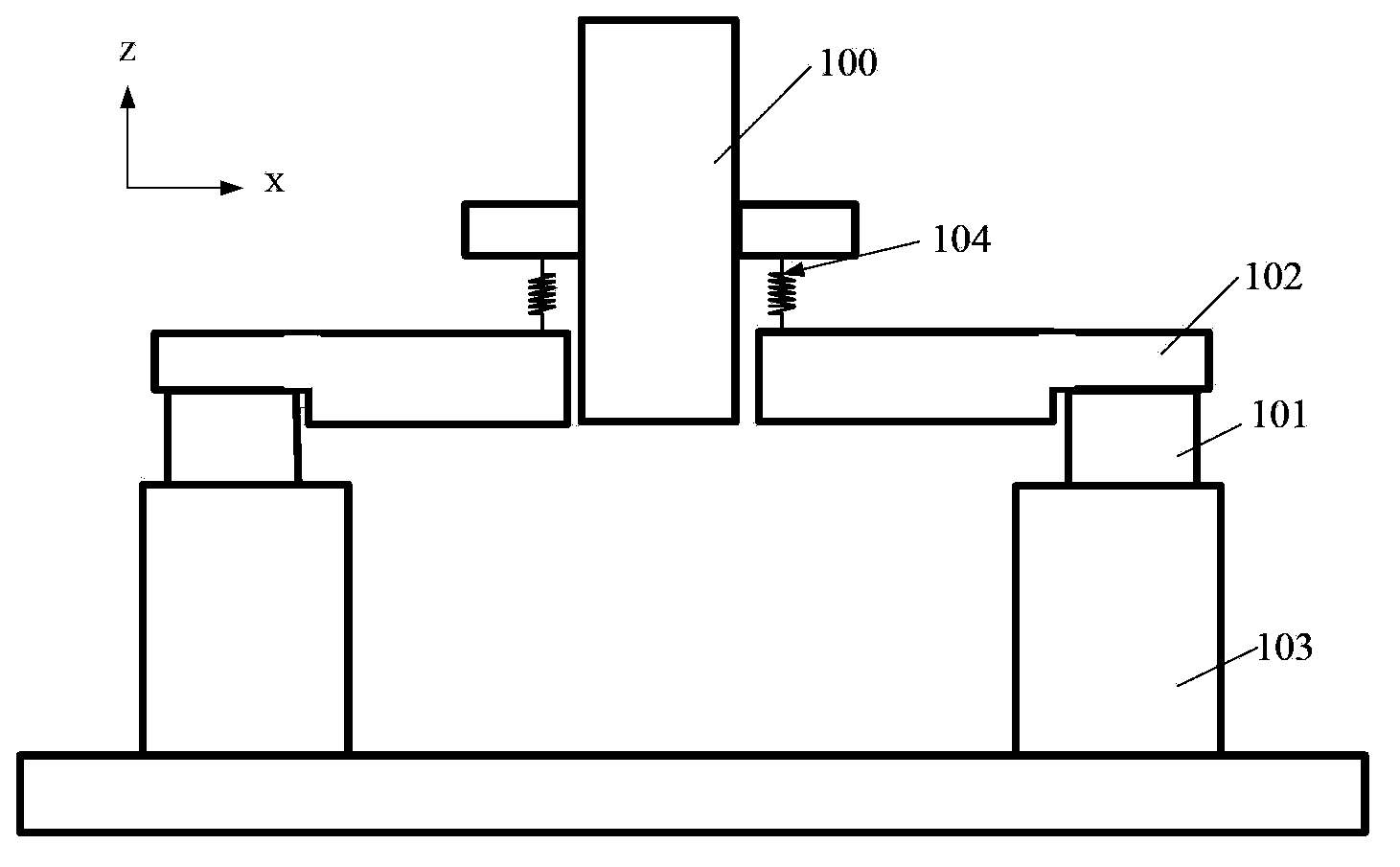
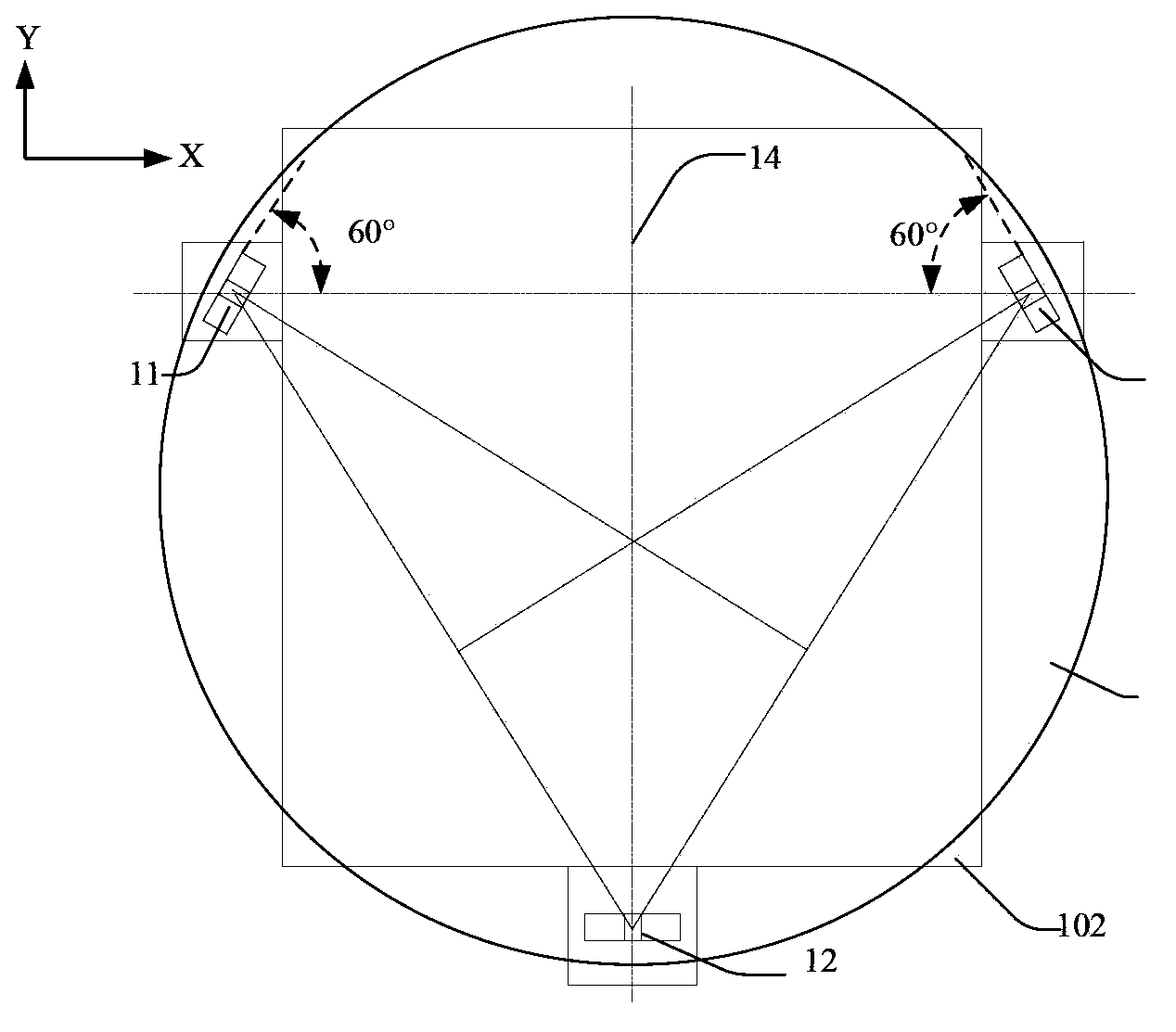
[0056] Such as image 3 As shown, the flexible support device of the present invention includes a first flexible support 11, a second flexible support 12 and a third flexible support 13, the three are distributed at three intersection points of an isosceles triangle, and the first flexible support 11 Located at the apex, the second flexible support 12 and the third flexible support 13 are located at two bottom points, and the center of the objective lens 100 coincides with the center of the triangle.

[0057] The first flexible support 11 is arranged laterally, the angle between the second flexible support 12 and the third flexible support 13 and the first flexible support 11 is 60°, the second flexible support 12 and the second flexible support 13 The three flexible supports 13 are arranged in a mirror image with the midline 14 of the apex as the axis.

[0058] Such as Figure 4 As shown, the flexible support device also includes a limit block 15 and a damper 16 correspondi...

Embodiment 2

[0067] Except for the following differences, all the others refer to Example 1.

[0068] Such as Figure 6 As shown, the first flexible support 11 is arranged vertically, and the second flexible support 12 and the third flexible support 13 are parallel to the first flexible support 11 .

[0069] Such as Figure 7 As shown, the first one-beam 246 in the first flexible connector 24 and the second flexible connector 25 replaces the first cross beam 243, and the second one-beam 247 replaces the second cross beam 245, and the hourglass shape shrinks The section 248 replaces the X-shaped constriction section 241, and a third I-beam 249 is provided at the narrowest point of the hourglass-shaped constriction section 248.

Embodiment 3

[0071] Except for the following differences, all the others refer to Example 1.

[0072] Such as Figure 8 As shown, the first flexible support 11 is arranged horizontally or vertically, and the second flexible support 12 and the third flexible support 13 are perpendicular to the first flexible support 11 . The flexible supporting device does not include the limit block 15 and the damper 16 .

[0073] Such as Figure 9 As shown, the structure of the first flexible support 11, the second flexible support 12 and the third flexible support 13 is the same, taking the first flexible support 11 as an example, it includes a top block 21 connected to the objective lens 100, a flexible The connection mechanism and the first bottom block group 31 and the second bottom block group 32 connected with the main substrate 102 .

[0074] The first bottom block group 31 and the second bottom block group 32 have the same structure, taking the first bottom block group 31 as an example, it incl...


PUM

PropertyMeasurementUnit
Angleaaaaaaaaaa
Thicknessaaaaaaaaaa
Wall thicknessaaaaaaaaaa

Abstract

The invention belongs to a flexible supporting device and flexible supporting pieces of a photoetching machine. Each flexible supporting piece comprises a top block, a flexible connecting mechanism and bottom blocks, wherein the top block is connected with an objective lens; the bottom blocks are connected with a main base plate; the flexible connecting mechanism comprises two flexible connecting pieces; the flexible connecting pieces are arranged between the top block and the bottom blocks to form a herringbone or inverted-T-shaped flexible supporting piece; each flexible connecting piece is a frame structure with an internal beam or a beam structure with a flexible hinge. The flexible supporting device comprises a first flexible supporting piece, a second flexible supporting piece and a third flexible supporting piece, wherein the three flexible supporting pieces are distributed at three intersection points of an isosceles triangle; the objective lens is arranged in the center of the triangle. According to the technical scheme provided by the invention, the overall modal of an assembly of the objective lens and the main base plate is smaller than 30Hz by virtue of the adopted flexible supporting pieces and the positional layout of the flexible supporting pieces. Each flexible supporting piece is ultralow in rigidity and sufficient in supporting strength, and meanwhile, the stress concentration is avoided.

Description

technical field [0001] The invention belongs to photoetching machine equipment, and in particular relates to a flexible support device and a flexible support member of a photoetching machine. Background technique [0002] The lithography machine mainly uses the workpiece table to carry silicon wafers or glass substrates, etc., to move synchronously with the mask table under the objective lens, and complete precise exposure work. [0003] During the working process of the lithography machine system, the workpiece table and the mask table are respectively based on the two sides and one axis (object plane, focal plane and optical axis) of the projection objective lens. Driven by the control system, the workpiece table and the mask table are realized according to the required precision. The relative position between the mask tables, and the position of the two relative to the objective lens. Due to the high positioning accuracy and high synchronous motion accuracy of the lithog...

Claims


Application Information

Patent Timeline
IPC IPC(8): F16F15/02G03F7/20
Inventor 王茜王璟秦磊
Owner SHANGHAI MICRO ELECTRONICS EQUIP (GRP) CO LTD
Why Eureka
Try Eureka