Case circular discontinuous energy concentrating jet flow cracker
A concentrated energy jet, discontinuous technology, applied in the direction of mining fluid, wellbore/well components, blasting, etc., to achieve the effects of small vibration, lower production costs, and less priming charge
- Summary
- Abstract
- Description
- Claims
- Application Information
AI Technical Summary
Problems solved by technology
Method used
Image
Examples
Embodiment 1
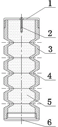
[0024] see figure 1 with figure 2 , choose a cylindrical aluminum tube with an outer diameter of φ10mm, a wall thickness of 1mm, and a length of 80mm as the cartridge case 3, and press out a tapered groove 4 with a depth of 1.5mm every 13mm on the outer surface of the cartridge case 3, the length of the busbar 2.82mm, cone angle 90°, a total of 5 grooves, 5mm and 10mm are reserved for the lower bottom and upper top respectively. Passivated RDX is used as the explosive 5 in the cartridge case, and the total charge is 6g. Both ends of the cartridge case 3 are provided with threaded structures to facilitate the connection with the cover. There is a through hole in the middle of the upper cover 1, from which the detonating cord 2 as the detonating device is drawn. Internal thread is arranged on the endoporus of last cover 1, and it cooperates with the external thread on the shell hole wall; There is external thread on the outer circle surface of lower cover 6, and it cooperat...
Embodiment 2
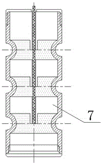
[0028] see image 3 , the outer diameter is φ12mm, the wall thickness is 1mm, and the cylindrical copper tube with a length of 80mm is used as the shell 3, and the aluminum block with a through hole in the middle is used as the charge layerer 7, and three lines are pressed on the outer surface of the shell 3. For the semicircular groove 4 of φ4mm, the spacing between the two grooves is 20mm, and 8mm and 12mm are reserved for the lower bottom and the upper top respectively. Titanium ammonium is housed in the shell as charge 5, and the total charge is 3g. Both ends of the cartridge case 3 are provided with threaded structures to facilitate the connection with the cover. There is a through hole in the middle of the upper cover 1, from which the detonating cord 2 as the detonating device is drawn. There is external thread on the outer circular surface of lower cover 6, and it cooperates with the internal thread on the shell hole wall.
[0029] Use the product of this embodiment...
Embodiment 3
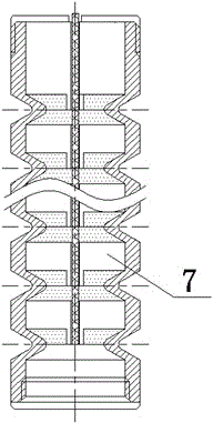
[0032] see Figure 4, choose a cylindrical copper tube with an outer diameter of φ16mm, a wall thickness of 1mm, and a length of 320mm as the shell 3, and press a tapered groove 4 with an outer diameter of 4mm and a depth of 1.5mm every 20mm, the length of the busbar is 2.21mm, and the cone top The angle is 60°, 14 in total. With RDX: emulsion explosive = 80%: 20% as the main charge, detonate directly with the nonel.
[0033] Using the 14 rows of casing circumferential discontinuous energy-concentrating jet crackers of this embodiment to carry out a cutting blast simulation test on a cement pier cast in a seamless steel pipe: a deep hole with a diameter of φ25mm and a length of 500mm is processed in the center of the cement pier , 6 deep holes with a diameter of φ25mm and a length of 500mm are processed on a circle with a center diameter of φ70mm, and the diameter of the cement pier is φ310mm and a length of 500mm. Put the above shell circumferential groove explosion shaped ...
PUM
 Abstract
Description
Claims
Application Information
 - R&D
- Intellectual Property
- Life Sciences
- Materials
- Tech Scout
- Unparalleled Data Quality
- Higher Quality Content
- 60% Fewer Hallucinations
Browse by: Latest US Patents, China's latest patents, Technical Efficacy Thesaurus, Application Domain, Technology Topic, Popular Technical Reports.
© 2025 PatSnap. All rights reserved.Legal|Privacy policy|Modern Slavery Act Transparency Statement|Sitemap|About US| Contact US: help@patsnap.com


