Method for observing inner shearing zone of zirconium base amorphous alloy

A zirconium-based amorphous alloy and shear band technology, which is applied in the preparation of test samples and other directions, can solve the problems of unfavorable shear band formation and evolution research, warping, cracks, curling, etc.

Inactive Publication Date: 2014-08-13
TAIYUAN UNIVERSITY OF SCIENCE AND TECHNOLOGY
View PDF5 Cites 9 Cited by
  • Summary
  • Abstract
  • Description
  • Claims
  • Application Information

AI Technical Summary

Problems solved by technology

At present, those skilled in the art study the shear band mainly by directly observing the shear steps on the side surface of the zirconium-based amorphous alloy specimen during the deformation process or after the deformation, but during the deformation process, especially The side surfaces of large plastic deformation specimens often have curling, warping and cracks, etc., and it is difficult...

Method used


Image

  • Method for observing inner shearing zone of zirconium base amorphous alloy
  • Method for observing inner shearing zone of zirconium base amorphous alloy

Examples


Embodiment 1

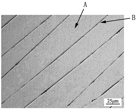
[0017] (1) The zirconium-based amorphous alloy specimen is rolled and deformed by a two-roll rolling mill, and the deformation is 20%;

[0018] (2) Using water as a wetting agent, use 400#, 800#, and 1200# silicon carbide water sandpaper to grind the zirconium-based amorphous alloy specimens plastically deformed in step (1) step by step, and remove the specimens Obtain at least one observation plane for the severely deformed part of the outer surface; each time after changing the sandpaper, turn the observation plane on the specimen 90 degrees in parallel and then grind until the scratches of the previous process are worn away, and each time before changing the sandpaper Clean the specimen with water;

[0019] (3) Place the zirconium-based amorphous alloy specimen ground in step (2) in a polishing machine, and use diamond polishing paste with a particle size of 5 μm and 1 μm to mechanically polish the observation plane of the specimen in sequence;

[0020] (4) Etching the obs...

Embodiment 2

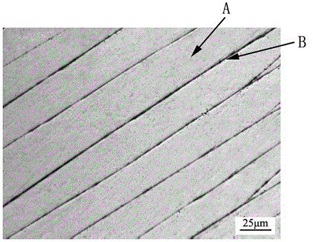
[0023] (1) A zirconium-based amorphous alloy specimen is rolled and deformed by a two-roll rolling mill, and the deformation is 30%;

[0024] (2) Using water as a wetting agent, use 400#, 800#, and 1200# silicon carbide water sandpaper to grind the zirconium-based amorphous alloy specimens plastically deformed in step (1) step by step, and remove the specimens Obtain at least one observation plane for the severely deformed part of the outer surface; each time after changing the sandpaper, turn the observation plane on the specimen 90 degrees in parallel and then grind until the scratches of the previous process are worn away, and each time before changing the sandpaper Clean the specimen with water;

[0025] (3) Place the zirconium-based amorphous alloy specimen ground in step (2) in a polishing machine, and use diamond polishing paste with a particle size of 5 μm and 1 μm to mechanically polish the observation plane of the specimen in sequence;

[0026] (4) Etching the obser...


PUM


Abstract

The invention discloses a method for observing inner shearing zone of zirconium base amorphous alloy, and belongs to the technical field of metal material micro-structure observation. The method is characterized by comprising the following steps: (1) carrying out plastic deformation on zirconium base amorphous alloy through rolling; (2) carrying out step-by-step grinding on the plastically-deformed zirconium base amorphous alloy test-piece to obtain at least one observation surface; (3) carrying out mechanical polishing on the observation surface of the test-piece; (4) etching the polished observation surface of the test-piece; (5) observing the morphology of the inner shearing zone of the test-piece through an optical microscope. The observation method overcomes the shortages of conventional methods that directly use a scanning electron microscope to observe a test-piece surface or use a transmission electron microscope to observe the test-piece interior, is capable of clearly observing the morphology and distributions of shearing zones in deformed zirconium base amorphous alloy, is easy and practicable, and does not need special equipment.

Description

technical field [0001] The invention belongs to the technical field of metal material microstructure observation, and in particular relates to a method for observing shear bands inside zirconium-based amorphous alloys. Background technique [0002] The plastic deformation of amorphous alloys is divided into uniform deformation and non-uniform deformation. At high temperature or very low strain rate, it is mainly uniform deformation, and all atoms participate in macroscopic deformation; at low temperature or high strain rate, it is mainly non-uniform deformation. Deformation, plastic deformation is highly confined to a very narrow shear band region, that is to say, a small number of atoms participate in the macroscopic deformation. Since amorphous alloys do not have the dislocation system and grain structure in traditional metal materials, their plastic deformation at room temperature is mainly accomplished through the nucleation and expansion of shear bands, so the formation...

Claims


Application Information

Patent Timeline
IPC IPC(8): G01N1/32G01N1/30C22C45/10
Inventor 胡勇闫红红李永堂闫志杰
Owner TAIYUAN UNIVERSITY OF SCIENCE AND TECHNOLOGY
Why Eureka
Try Eureka