
Automatic pipe cutting machine

A pipe cutting machine, automatic technology, applied in the direction of metal processing, etc., can solve the problems of large repeated positioning errors, potential safety hazards, large saw kerf, etc., and achieve the effect of precise positioning

Active Publication Date: 2014-08-20
XIANGYANG YISHUN ELECTROMECHANICAL TECH
View PDF6 Cites 15 Cited by
  • Summary
  • Abstract
  • Description
  • Claims
  • Application Information

AI Technical Summary

Problems solved by technology

[0003] At present, square pipe cutting is mainly manual cutting machine cutting and semi-automatic cutting, both of which have a high scrap rate, and the cut products have poor precision and poor product consistency.
Manual cutting has the disadvantages of high labor intensity, poor environment, potential safety hazards, large errors in cut products, and large saw kerfs.
Semi-automatic cutting has the following disadvantages: (1) Each tube material needs to be manually placed in the feeding fixture, and the head section of each tube material still needs to be manually positioned; (2) The material is fed from the second section of cutting The mechanism adopts servo, hydraulic, pneumatic and other power feeding methods. The length of each feeding is limited by the length of the linear guide rail, which does not exceed 500mm. When the product to be cut is long, it needs to be clamped and fed multiple times, which will affect the production efficiency and accuracy, and the efficiency is low. , the repeated positioning error is large, and it needs to be clamped and fed multiple times when cutting a long product. In this way, the cumulative error of repeated clamping, positioning, and feeding is large, and the precision of the cut product is poor; (3) The raw material of each tube is cut to the end When one section is less than the length of a product, the machine cannot handle it automatically, and it is necessary to manually install a tail rod at the end of the material. The clamping of the tail rod affects production efficiency, and different specifications of pipe materials need to be made of different specifications of tail rods, which requires both investment and Increase management costs; (4) The feeding servo mechanism and manual positioning of the first section, repeated pinch feeding of long materials cannot guarantee product consistency and waste servo precision
The role of the automatic machine cannot be fully utilized, and workers often have to go to the cutting position to deal with the tailings, which affects the number of machines and work efficiency for one person to take care of the machine, and there are potential safety hazards

Method used


Image

  • Automatic pipe cutting machine
  • Automatic pipe cutting machine
  • Automatic pipe cutting machine

Examples


Embodiment 1

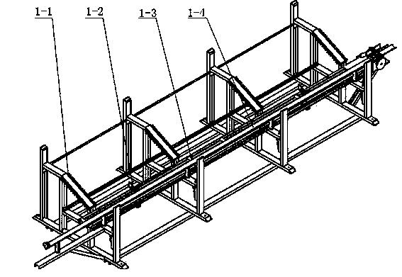
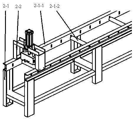
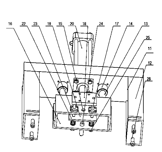
[0024] Example 1 as Figure 1 to Figure 5 , Figure 8 , Figure 9 shown. Embodiment 1 is composed of a storage and distribution rack, a retrieving mechanism, a feeding track 1-3, a pushing system 1-4, a cutting system including an automatic clamping mechanism and an automatic cutting mechanism, and a cut and blanking system. The storage and distribution rack is provided with an inclined track 1-1 and a positioning block for retrieving materials. The positioning block for retrieving materials is a folded plate. The vertical part is connected to the column on the inclined track close to the feeding track through a screw, and the upper part is folded at an angle. Make it perpendicular to the inclined track, and adjust the height of the part above the inclined track surface according to the specifications of the pipe material, which is different from the prior art. The feeding track 1-3 is arranged in parallel with the pushing system track, and is fixed on a plane. The first f...

Embodiment 2

[0026] Example 2 as Image 6 , Figure 7 shown. Automatic pipe cutting machine tail processing mechanism 4-2 such as Image 6 Shown, is prior art. The automatic pipe cutting machine material tail processing mechanism 4-2 is installed on the blanking frame 4-1 close to the automatic clamping and cutting part on the blanking frame 4-1 through the material tail processing mechanism mounting plate 4-3. The mounting plate 4-3 is drilled with a through hole so that the material tail processing mechanism 4-2 is connected on it by a screw rod. The bottom plate of the material tail processing mechanism 4-2 has a flat hole, which can adjust its position relative to the center line of the cutting track of the automatic cutting machine according to the square tube raw material specifications to be cut. The fixed-length positioning mechanism 4-0 is contained on the rear side beam of the blanking frame 4-1.

[0027] Tail processing mechanism 4-2 such as Figure 7 Shown, is prior art. ...


PUM


Abstract

The invention relates to an automatic pipe cutting machine and belongs to the technical field of pipe cutting equipment. The automatic pipe cutting machine mainly solves the problem that an existing pipe cutting machine is not suitable for cutting square pipes. The automatic pipe cutting machine is mainly characterized by comprising an automatic material storage and distribution frame, an automatic material taking mechanism, a material conveying rail, a material pushing system, a cutting system, a sizing and locating mechanism and a discharging frame, wherein the cutting system comprises an automatic clamping mechanism and an automatic cutting mechanism; the sizing and locating mechanism is composed of a sizing and locating box, a large guide rod, an upper girder, uprights, an oil cylinder and a large linear bearing; the sizing and locating box comprises a front panel, a rear panel, a small linear bearing, a small guide rod, a locating striking board, a spring pressing board, a spring clamp, a nut, a spring and a sensor; the uprights at the two sides of the sizing and locating mechanism are fixed to beams at the two sides of the upper end of the discharging frame respectively. The automatic pipe cutting machine has the advantages that the length of a product needing cutting is not limited, automatic material distribution, automation material taking, automatic material conveying and automatic clamping are achieved, and the automatic pipe cutting machine is mainly used for automatically cutting rectangular pipes.

Description

technical field [0001] The invention belongs to the technical field of pipe cutting equipment. In particular, it relates to an automatic pipe cutting machine which is especially suitable for cutting rectangular pipes. Background technique [0002] The raw material of the pipe material is automatically taken to the feeding track by the feeding mechanism on the storage and distribution rack of the automatic pipe cutting machine, and the pushing system automatically pushes it forward until it reaches the positioning and sizing mechanism on the blanking rack. The sizing mechanism accurately determines the sizing and positioning, and sends a signal to the controller, and the cutting system completes automatic clamping and automatic cutting. Each cut product is passed to the next process by the blanking rack or falls into the lower box of the blanking rack. Every time a pipe material is cut, its tail is pushed into the tail box, and in one case, it is automatically pushed into t...

Claims


Application Information

Patent Timeline
IPC IPC(8): B23Q7/00
CPCB23Q7/00
Inventor 解邦银章文彬
Owner XIANGYANG YISHUN ELECTROMECHANICAL TECH
Learn More