
Double-cyclone coal pyrolysis gasification step converting device and double-cyclone coal pyrolysis gasification step converting method

A conversion device and double cyclone technology, which is applied in the gasification of granular/powder fuel, the manufacture of combustible gas, the petroleum industry, etc., can solve the problem of not being able to reasonably recover the high temperature sensible heat of coal gas, and achieve high-efficiency coal pyrolysis gasification classification conversion , mild reaction conditions, high pyrolysis efficiency

Active Publication Date: 2014-08-20
HARBIN INST OF TECH
View PDF6 Cites 20 Cited by
  • Summary
  • Abstract
  • Description
  • Claims
  • Application Information

AI Technical Summary

Problems solved by technology

[0008] In order to solve the problem that the existing gasification furnace cannot reasonably recycle and utilize the high-temperature sensible heat of the coal gas produced by the entrained-flow gasification furnace, the present invention proposes a double-cyclone coal pyrolysis gasification graded conversion device and method

Method used


Image

  • Double-cyclone coal pyrolysis gasification step converting device and double-cyclone coal pyrolysis gasification step converting method
  • Double-cyclone coal pyrolysis gasification step converting device and double-cyclone coal pyrolysis gasification step converting method
  • Double-cyclone coal pyrolysis gasification step converting device and double-cyclone coal pyrolysis gasification step converting method

Examples


specific Embodiment approach 1

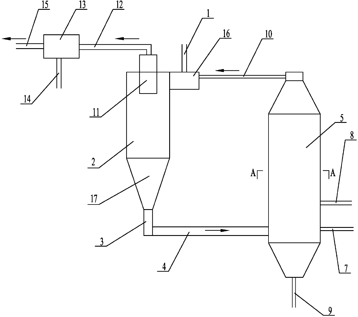
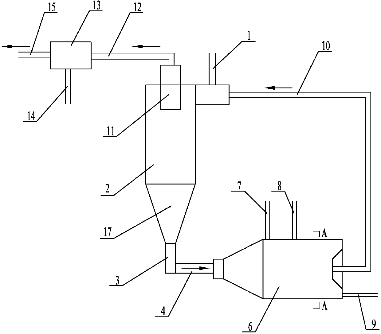
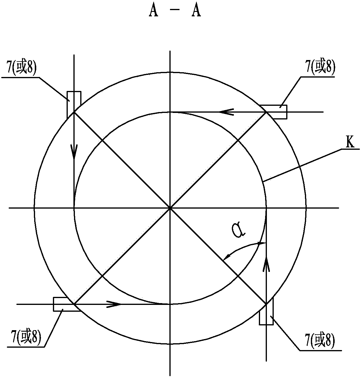
[0021] Specific implementation mode one: combine figure 1 and figure 2 This embodiment is described. This embodiment includes a cyclone pyrolysis furnace 2, a feeding device 3, a pyrolysis semi-coke channel 4, a cyclone gasification furnace 5, a high-temperature crude gas channel 10, a cyclone pyrolysis furnace exhaust pipe 11, and a pyrolysis furnace. Gas mixing channel 12, cooling device 13, crude synthesis gas connecting pipe 15, coal feeding connecting pipe 16, material legs 17, several oxidant nozzles 7 and several steam nozzles 8, coal feeding connecting pipe 16 is installed on the upper end of cyclone pyrolysis furnace 2 , the exhaust pipe 11 of the cyclone pyrolysis furnace is installed on the top of the cyclone pyrolysis furnace 2, and the coal inlet 16 is provided with a coal feeding inlet 1. One end of the semi-coke decomposing channel 4 communicates with the feed-reversing device 3, the other end of the pyrolysis semi-coke channel 4 communicates with the lower pa...

specific Embodiment approach 2

[0022] Specific implementation mode two: combination figure 1 and figure 2 The present embodiment will be described. The cyclone gasifier 5 of the present embodiment is a vertical cyclone gasifier or a horizontal cyclone gasifier. The vertical wind gasifier is suitable for gasifying pulverized coal with small particle size, and the horizontal cyclone gasifier is suitable for gasifying coal particles with large particle size. Other components and connections are the same as those in the first embodiment.

specific Embodiment approach 3

[0023] Specific implementation mode three: combination figure 1 and figure 2 To illustrate this embodiment, the dipleg 17 of this embodiment is conical, the diameter of the upper end of the cone is larger than the diameter of the lower end, and the height of the dipleg 17 is 1m-2m. The longer material leg 17 can play a sealing role to ensure the pressure difference between the cyclone pyrolysis furnace 2 and the cyclone gasification furnace 5 . Other compositions and connections are the same as those in Embodiment 1 or 2.

[0024] Specific implementation mode four: combination figure 1 and figure 2 Describe this implementation mode, this implementation mode is realized through the following steps:

[0025]Step 1: The pulverized coal enters the coal inlet connecting pipe 16 from the coal feeding inlet 1, and the pulverized coal uses liquid or gas fuel in the high-temperature crude gas (system start-up stage), and injects the fuel from an ignition oil gun arranged near the...


PUM

PropertyMeasurementUnit
Particle sizeaaaaaaaaaa

Abstract

The invention discloses a double-cyclone coal pyrolysis gasification step converting device and a double-cyclone coal pyrolysis gasification step converting method, and relates to a combusting device and a combusting method. The device is characterized in that a cyclone pyrolyzing furnace is communicated with a cyclone gasifying furnace by a material backing device and a pyrolyzing semi-coke channel; the cyclone gasifying furnace is communicated with the cyclone pyrolyzing furnace by a high-temperature raw coal gas channel; the cyclone pyrolyzing furnace is communicated with a cooling device by a pyrolyzing gas-mixing channel; an oxidant spray nozzle and a vapor spray nozzle are arranged on the outer wall of the cyclone gasifying furnace. The method is as follows: firstly, feeding coal dust into the cyclone pyrolyzing furnace under blocking and feeding of the high-temperature raw coal gas; secondly, pyrolyzing the coal dust in the cyclone pyrolyzing furnace, exhausting the pyrolyzed gas mixture into the cooling device, cooling, and conveying back the pyrolyzed semi-coke to the cyclone gasifying furnace; thirdly, spraying the oxidant and the vapor into the cyclone pyrolyzing furnace by the oxidant spray nozzle and the vapor spray nozzle at the same time, wherein the produced high-temperature raw coal gas is re-fed into the cyclone pyrolyzing furnace as a coal pyrolyzing gas heater carrier; coal residue in the cyclone gasifying furnace is exhausted through an ash residue discharge hole in the form of solid or liquid. The double-cyclone coal pyrolysis gasification step converting device and the double-cyclone coal pyrolysis gasification step converting method are used for gasifying clean coal gas.

Description

technical field [0001] The invention relates to a combustion device and method, in particular to a double-cyclone coal pyrolysis gasification graded conversion device and method. Background technique [0002] Entrained bed gasification technology has become the main development direction of modern coal gasification technology because of its advantages of large processing capacity, high carbon conversion rate, and high cold gas efficiency. The characteristics of high temperature, high pressure and good mixing in the furnace determine that it has the greatest potential to increase production capacity per unit time and unit volume, which is in line with the development trend of large-scale chemical equipment. However, this technology also faces some important problems: [0003] (1) Large-scale is the primary issue in the development of coal gasification technology. Due to the limitations of objective factors such as manufacturing, transportation, and installation, it is neces...

Claims


Application Information

Patent Timeline
IPC IPC(8): C10J3/66C10J3/84C10J3/56C10J3/54
Inventor 邱朋华徐健健刘栗李丹丹刘欢鹏吴少华
Owner HARBIN INST OF TECH
Learn More