Packing Leakage Protection of Reciprocating Piston Compressor Gas Distribution Station

A technology of reciprocating pistons and compressors, applied in the field of gas distribution stations, can solve the problems of difficult installation of piping, pollution of lubricating oil, hidden safety hazards, etc., and achieve the effect of compact structure

Inactive Publication Date: 2015-12-09
金凯威(廊坊)压缩机有限公司
View PDF7 Cites 0 Cited by
  • Summary
  • Abstract
  • Description
  • Claims
  • Application Information

AI Technical Summary

Problems solved by technology

[0002] The piston rod packing of the reciprocating piston compressor will leak during operation. If the working medium in the compressor is flammable, explosive or toxic gas, the gas will leak into the factory building, which will cause safety hazards. If it leaks to the machine lubrication In the oil tank, it will also pollute the lubricating oil and affect the transmission mechanism of the compressor
[0003] Usually, the compressor is equipped with packing leakage protection gas distribution station, which is used to replace the main packing, intermediate packing, pre-filling and intermediate intermediate sleeve with nitrogen gas. In the traditional packing leakage protection system, each pipeline is separated. The piping is complicated, the pipes are easy to cross and interfere with each other, the installation of the piping is difficult, it is not easy to distinguish the specific function of each pipeline, and the maintenance is not convenient

Method used


Image

  • Packing Leakage Protection of Reciprocating Piston Compressor Gas Distribution Station
  • Packing Leakage Protection of Reciprocating Piston Compressor Gas Distribution Station
  • Packing Leakage Protection of Reciprocating Piston Compressor Gas Distribution Station

Examples


Embodiment Construction

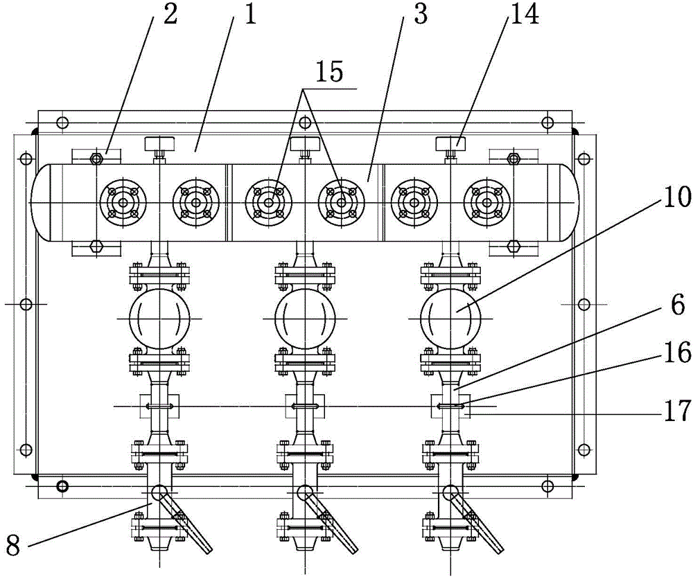
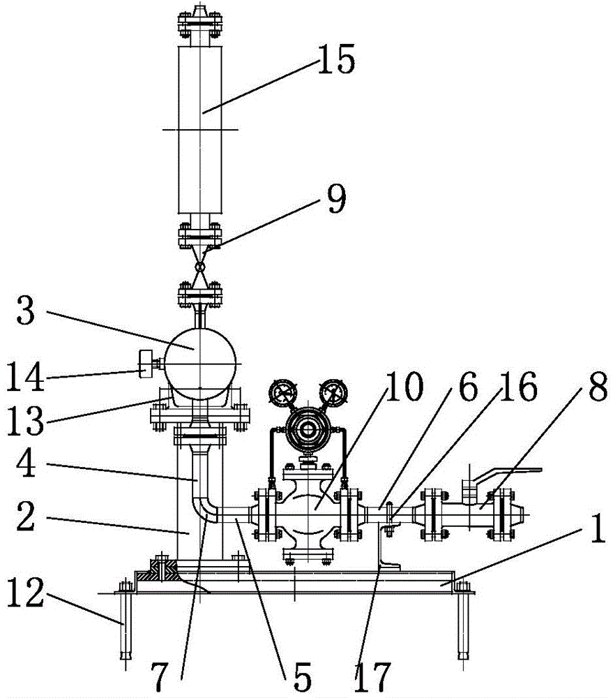
[0016] combine figure 1 and figure 2 As shown, the reciprocating piston compressor filling leakage protection gas distribution station of the present invention includes a chassis 1, a pillar 2, and a gas collection tank 3, and also includes a first seamless steel pipe 4, a second seamless steel pipe 5, and a third seamless steel pipe with the same number. Seam steel pipe 6, long radius elbow 7, first ball valve 8, second ball valve 9, pressure reducing valve 10 and support frame 17, chassis 1 is fixedly installed on the ground through expansion bolts 12, and the rear end of chassis 1 is provided with two pillars 2. The lower end of each pillar 2 is connected to the chassis 1 by bolts, and the upper end of each pillar 2 is provided with an air collecting tank tray 13, and the air collecting tank 3 is arranged on the tray 13, and the inside of the air collecting tank 3 is divided into left , middle and right areas, each area of ​​the gas collection tank 3 is connected with a s...


PUM


Abstract

The invention discloses a filler leakage protection gas distribution station of a reciprocating piston type compressor and relates to the gas distribution station for protecting safe operation of the reciprocating piston type compressor. The gas distribution comprises a chassis, support poles, and a gas collection tank, wherein the chassis is fixed on the ground; the support poles are arranged at the rear end of the chassis; the lower end of each support pole is connected on the chassis; a pallet is arranged at the upper end of each support pole; the gas collection tank is arranged on the pallet and is partitioned into a left zone, a middle zone and a right zone; a second ball valve is connected at the upper end of each zone; two second ball valves of the middle zone are connected with a floater flow meter; a first seamless steel pipe, which is vertically arranged, is separately connected with the lower end of each zone; a long-radius elbow, a second seamless steel pipe, a reducing valve and a third seamless steel pipe are connected with the other ends of the three seamless steel pipes in sequence; the other end of the third seamless steel pipe is connected with the outlet end of the first ball valve through a flange; the inlet end of the first ball valve is connected with a nitrogen gas source; and the third seamless steel pipe is fixed on a support which is fixed on the chassis and the second and third seamless steel pipes are horizontally arranged.

Description

technical field [0001] The invention relates to a gas distribution station, in particular to a gas distribution station for protecting the safe operation of a reciprocating piston compressor. Background technique [0002] The piston rod packing of the reciprocating piston compressor will leak during operation. If the working medium in the compressor is flammable, explosive or toxic gas, the gas will leak into the factory building, which will cause safety hazards. If it leaks to the machine lubrication In the oil tank, the lubricating oil will also be polluted, which will affect the transmission mechanism of the compressor. [0003] Usually, the compressor is equipped with packing leakage protection gas distribution station, which is used to replace the main packing, intermediate packing, pre-filling and intermediate intermediate sleeve with nitrogen gas. In the traditional packing leakage protection system, each pipeline is separated. The piping is complicated, the pipes ar...

Claims


Application Information

Patent Timeline
Patent Type & Authority Patents(China)
IPC IPC(8): F17C5/02
Inventor 赵晓彬李瑞琴
Owner 金凯威(廊坊)压缩机有限公司
Why Eureka
Try Eureka