Rectifying circuit and power supply circuit
A technology of rectification circuit and external power supply, which is applied in the field of rectification circuit and power supply circuit, and can solve problems such as slow conduction of diodes
- Summary
- Abstract
- Description
- Claims
- Application Information
AI Technical Summary
Problems solved by technology
Method used
Image


Examples
no. 1 approach )
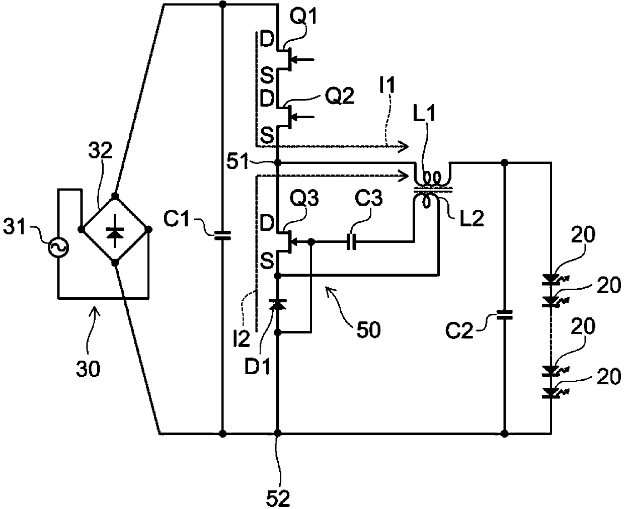
[0021] figure 1 It is a circuit diagram of a power supply circuit using the rectifier circuit 50 of the first embodiment.
[0022] figure 1 2 illustrates a step-down DC-DC converter (step-down converter) as an example of a power supply circuit.
[0023] The step-down converter alternately turns on and off the high-side switching elements Q1 and Q2 connected to the DC power supply 30 and the rectification circuit 50 , thereby outputting a voltage lower than the input voltage from the DC power supply 30 to the load.
[0024] The load is, for example, the light emitting element 20 . The light emitting element 20 is, for example, an LED (Light Emitting Diode). In addition, as the light-emitting element 20 , besides the LED, an organic light-emitting diode (Organic Light Emitting Diode: OLED), an inorganic electroluminescence (Inorganic ElectroLuminescence) light-emitting element, an organic electroluminescence (Organic ElectroLuminescence) light-emitting element, or other elect...
no. 2 approach )
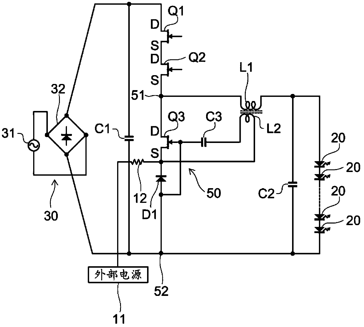
[0064] image 3 It is a circuit diagram of the power supply circuit of 2nd Embodiment.
[0065] In the second embodiment, a step-down converter is exemplified as a power supply circuit. In the step-down converter of the second embodiment, the external power supply 11 is connected to the source electrode of the switching element Q3 and the cathode of the diode D1 via the resistor 12 . other structures with figure 1 The step-down converters shown are the same and operate in the same way.
[0066] The resistor 12 functions as a limiting element that limits the current flowing from the auxiliary winding L2 to the external power supply 11 .
[0067] Figure 4 As shown in (b), a diode 13 can be used as such a limiting element. The diode 13 regards the direction from the external power supply 11 toward the source electrode of the switching element Q3 as the forward direction, and is connected between the external power supply 11 and the source electrode of the switching element ...
PUM
 Abstract
Description
Claims
Application Information
 - R&D
- Intellectual Property
- Life Sciences
- Materials
- Tech Scout
- Unparalleled Data Quality
- Higher Quality Content
- 60% Fewer Hallucinations
Browse by: Latest US Patents, China's latest patents, Technical Efficacy Thesaurus, Application Domain, Technology Topic, Popular Technical Reports.
© 2025 PatSnap. All rights reserved.Legal|Privacy policy|Modern Slavery Act Transparency Statement|Sitemap|About US| Contact US: help@patsnap.com