Methanation fluidized bed reactor

A fluidized bed reactor and methanation technology, applied in chemical instruments and methods, chemical/physical processes, petroleum industry, etc., can solve the problems of high reaction temperature, poor safety and reliability, increase product concentration, etc., and reach the reaction temperature Low cost, less equipment, and reduced consumption

Active Publication Date: 2014-08-27
尹明大
View PDF2 Cites 21 Cited by
  • Summary
  • Abstract
  • Description
  • Claims
  • Application Information

AI Technical Summary

Problems solved by technology

[0010] ①The reaction temperature is high, the equipment material requirements are high, and the safety is poor
If CO and CO in the inlet gas of the methanation reactor occur 2 When the content suddenly increases, the reactor is prone to over-temperature accidents, and the safety and reliability are poor
[0012] ② High catalyst cost
When the temperature is above 400°C, it is easy to produce carbon deposition reaction, which will cause carbon deposition on the surface of the catalyst, reduce the activity of the catalyst, and affect the service life of the catalyst
[0016] ④High power consumption
[0022] Current fluidized bed reactors, such as the methanation reaction device disclosed in Chinese patent application No. 20101023120.2, include fluidized bed reactors and fixed bed reactors, wherein in the fluidized bed reactor, the reacted gas and catalyst At the same time, it enters the gas-solid separator for separation. At this time, the separation efficiency is limited, and a large amount of catalyst cannot be recovered, and the gas after the reaction is connected to the output together.
The reactors all have the defects of uneven gas distribution, easy channeling, large bubbles, and high catalyst consumption.
[0023] Patent No. 201110023691.3 further sets up a cooling water spraying device to absorb the heat of reaction on the one hand and form a dilute phase region of solid particles in the upper space on the one hand, but spraying cooling water will make it more difficult to reuse the catalyst, which is not conducive to large-scale continuous production of
The reactor spray device increases the water concentration, which increases the product concentration and reduces the reaction conversion rate

Method used


Image

  • Methanation fluidized bed reactor
  • Methanation fluidized bed reactor
  • Methanation fluidized bed reactor

Examples


Embodiment 1

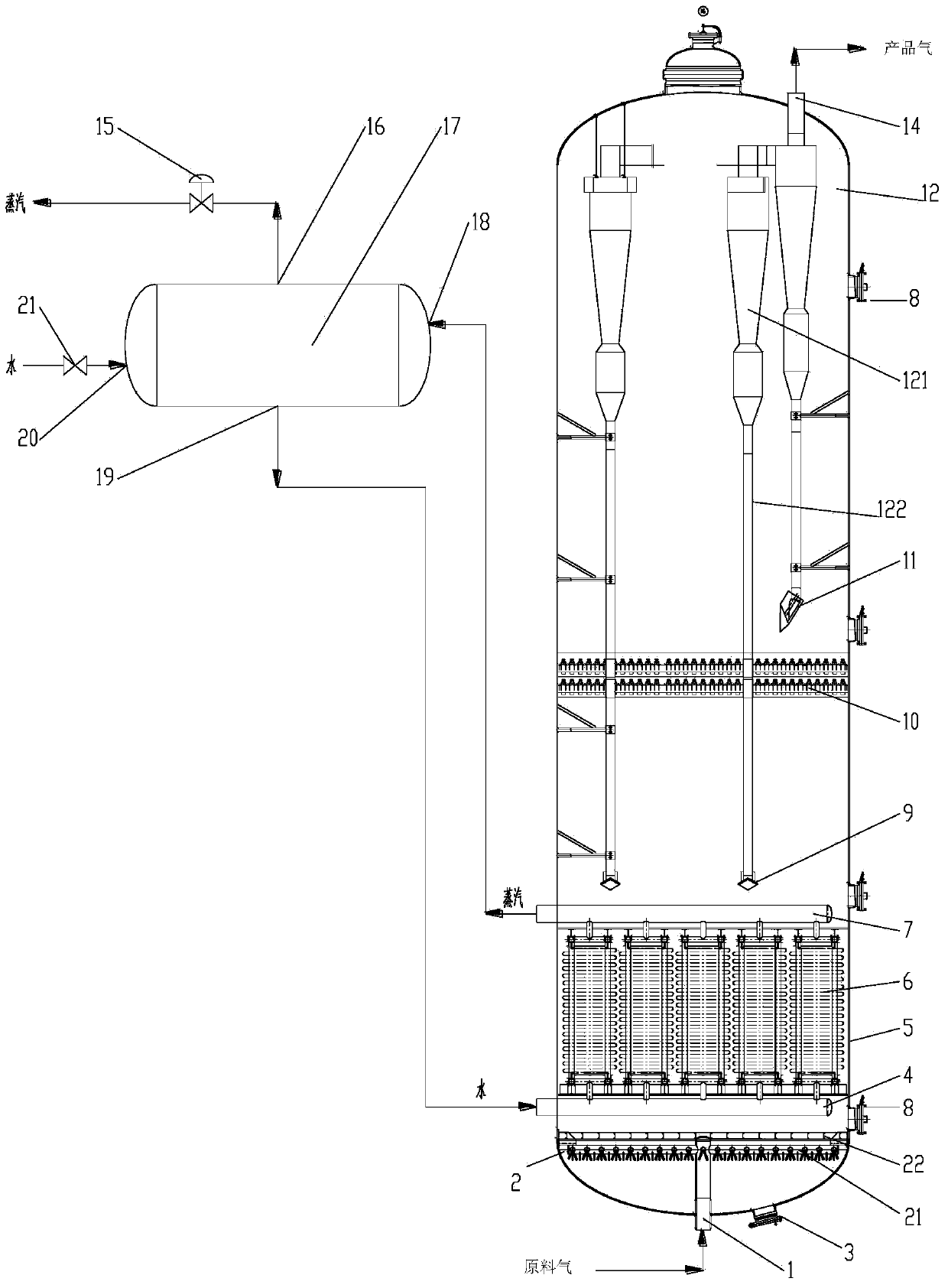
[0079] Such as figure 1 As shown, the fluidized bed reactor includes a vertical cylindrical shell 5 with both upper and lower ends of the head, the lower head of the cylindrical shell 5 is provided with a feed gas inlet 1, and the upper head of the shell 5 is A product gas outlet 14 is installed, and a gas distributor 2 is provided near the bottom of the inner space of the housing. The gas distributor 2 includes a primary gas distributor 21 and a secondary gas distributor 22. The primary gas distributor 21 includes multiple nozzles on substantially the same horizontal plane; the secondary gas distributor 22 is a plate with a plurality of openings, located above the primary gas distributor 21 . The plane in which the gas distributor 2 is located is substantially perpendicular to the longitudinal axis of the reactor.

[0080] The primary gas distributor 21 is directly connected with the feed gas inlet 1 through a pipeline. The gas input from the raw gas inlet is evenly distrib...

Embodiment 2

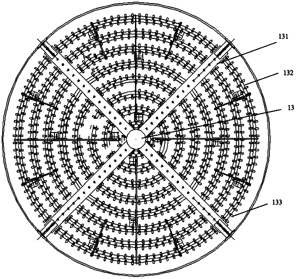
[0086] Such as figure 2 shown. The primary gas distributor 21 includes a plurality of annular pipes 132 distributed on the same plane, and the annular pipes are connected through radial branch pipes 131, and each radial branch pipe 131 is collected in the central pipe 13, and the central pipe 13 is the communication source gas Inlet piping with primary gas distributor. The nozzles 133 are connected to the annular pipe 132 and distributed with the ground.

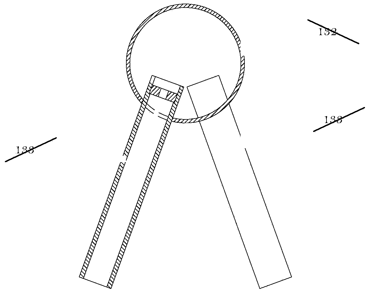
[0087] image 3 An enlarged view of the nozzle is shown. The nozzle 133 is connected to the annular pipe 132, and the opening of the nozzle 133 is downward; preferably, the nozzle includes a spray hole (only shown in the left nozzle, not shown in the right nozzle) and an extended pipeline located outside the spray hole, in a certain shape. Angled (eg, about 30°) toward the bottom of the reactor, the pipe walls between adjacent nozzles 133 are angled in opposite directions.

Embodiment 3

[0089] The preferred gas trap 10 includes a two-layer structure. Figure 4A A schematic diagram showing a preferred solution of a single-layer structure, in the same plane, consisting of protrusions arranged in different directions in the middle and on both sides. Figure 4B A magnified view of the protrusion arrangement is shown. Each bump is actually a claw-like intersection structure, such as Figure 4C shown.

[0090] The arrangement directions of the upper and lower two-layer structures are staggered at 90° (not shown in the figure).


PUM

PropertyMeasurementUnit
particle sizeaaaaaaaaaa
separationaaaaaaaaaa

Abstract

The invention provides a methanation fluidized bed reactor which is equipment for performing reaction on CO and H2 to generate methane and water and performing reaction on CO2 and H2 to generate methane and water at a certain constant low temperature. The methanation fluidized bed reactor comprises a cylindrical shell and inner parts, wherein a primary gas distributor and a secondary gas distributor are arranged at the bottom, and a catalyst is filled to form a catalyst bed; a heat exchange device consisting of a plurality of groups of heat exchange tubes is arranged in the catalyst bed; the lower ends of the heat exchange tubes in each group are communicated with a water inlet header pipe which is communicated with a water outlet of a steam drum, and the upper ends of the heat exchange tubes in each group are communicated with a steam outlet header pipe which is communicated with a steam inlet of the steam drum. According to the methanation fluidized bed reactor, heat continuously released during methanation reaction can be timely transferred through another medium, and the reaction can be performed at the constant low temperature.

Description

technical field [0001] The invention belongs to the field of chemical industry and relates to a fluidized bed reactor, in particular to a methanation fluidized bed reactor. Background technique [0002] At present, industrially synthesized natural gas mainly includes coke oven gas to natural gas and coal to natural gas. The key reaction of synthetic natural gas is methanation reaction, whose reaction formula is: [0003] CO+3H 2 =CH 4 +H 2 O △ H 298 =-206KJ / mol [0004] CO 2 +4H 2 =CH 4 +2H 2 O △ H 298 =-165KJ / mol [0005] The methanation reaction is a strongly exothermic reversible reaction. Under typical methanation reaction conditions, the adiabatic temperature rise per 1% CO conversion in the gas is about 72 °C, and every 1% CO 2 The adiabatic temperature rise for the conversion is about 60°C. [0006] In the existing methanation process, the methanation reactor is in the form of adiabatic reaction, that is, after the adiabatic reaction of the catalyst bed, ...

Claims


Application Information

Patent Timeline
Patent Type & Authority Applications(China)
IPC IPC(8): B01J8/24C10L3/08
Inventor 尹明大
Owner 尹明大
Why Eureka
Try Eureka