High-receiving-sensitivity passive RFID system with optical link connection

A technology of receiving sensitivity and optical link, applied in the field of passive RFID system, can solve the problems of small identification tag range and low identification accuracy, etc.

Active Publication Date: 2014-08-27
BEIJING UNIV OF POSTS & TELECOMM
View PDF3 Cites 8 Cited by
  • Summary
  • Abstract
  • Description
  • Claims
  • Application Information

AI Technical Summary

Problems solved by technology

[0006] The technical problem to be solved by the present invention is how to solve the problem that the range of identification tags existing in the existing passive RFID system is small and the identification accuracy is not high

Method used


Image

  • High-receiving-sensitivity passive RFID system with optical link connection
  • High-receiving-sensitivity passive RFID system with optical link connection
  • High-receiving-sensitivity passive RFID system with optical link connection

Examples


Embodiment 1

[0067] Embodiment 1, due to the addition of an optical link in the system, the input range of the optical link has certain requirements, and the optical link will also have a corresponding attenuation of the signal during transmission, so we are using the optical link In the process, a self-interference cancellation circuit is added to ensure the receiving sensitivity of the system, such as figure 2 shown.

[0068] Depending on the application, the figure 2 The shown self-interference elimination circuit is placed in different positions of the optical link to form different optical link structures.

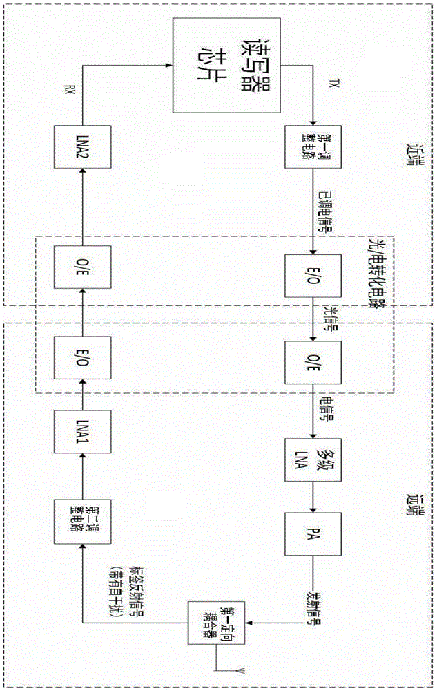
[0069] Passive RFID systems with high receiving sensitivity connected by optical links with self-interference cancellation circuits at both ends, such as image 3 As shown in , it is applied to scenarios where the remote antennas are widely distributed, the number of tags is large, and the surrounding environment is relatively complex.

[0070] The function of the self-interf...

Embodiment 2

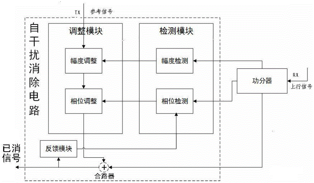
[0071] Embodiment 2, this embodiment provides a digitally controlled self-interference elimination circuit, such as Figure 4 shown.

[0072]The self-interference cancellation circuit is divided into four parts: detection module, adjustment module, feedback module and buffer. The detection module includes: an amplitude detection module, a phase detection module, and a control center. The adjustment module includes: an amplitude adjustment module and a phase adjustment module. The basic principle is: the uplink signal is input to the power divider, and the power divider divides the uplink signal into three paths, one path of large-amplitude signal is input to one of the inputs of the combiner, and the other two paths of small-amplitude signals are respectively input to the detection module In the amplitude detection module and phase detection module. Since the self-interference signal is much larger than the reflected tag signal in the uplink signal, the detection module is ...

Embodiment 3

[0076] Embodiment 3, the digital control provided by the present invention has a self-interference elimination circuit with a specific structure, such as Figure 6 shown.

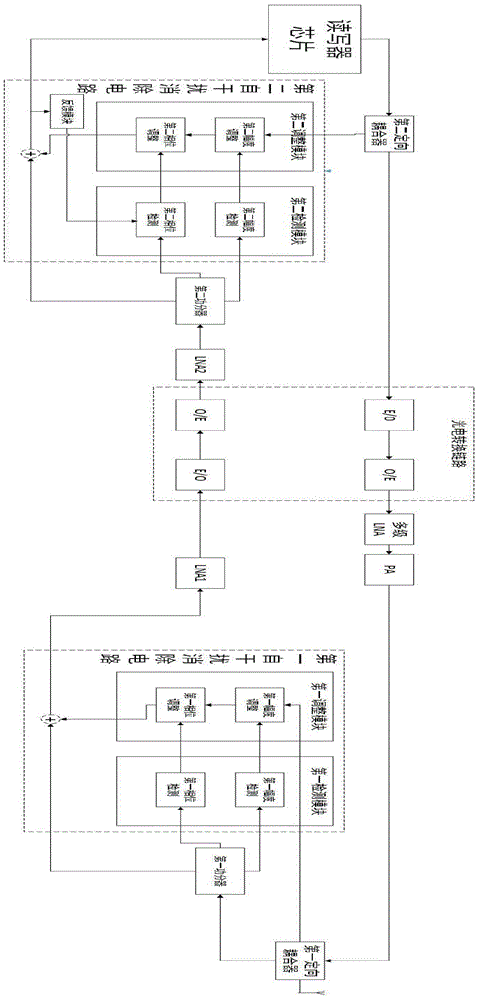
[0077] Passive RFID systems with high reception sensitivity connected by optical links with digitally controlled self-interference cancellation circuits with specific structures at both ends, such as Figure 7 As shown, there are three points of difference between the two ends in application:

[0078] 1. The near-end elimination effect is better than the far-end effect. Due to the limited space of the remote module and the large number of remote modules, in order to save costs, the remote self-interference cancellation module uses the simplest circuit form to eliminate the self-interference signal to a large extent, and the purpose is to make the uplink After the signal undergoes attenuation in the optical link, the back-end reader chip can still identify it. The near-end self-interference cancellation c...


PUM


Abstract

The invention relates to a high-receiving-sensitivity passive RFID system with optical link connection. By the adoption of an optical link structure, the high-receiving-sensitivity passive RFID system has the advantages of being easily applied to wiring in different environments, being very low in optical link loss under a long-distance transmission circumstance, being suitable for transmission of large volumes of data and the like, and therefore the distribution range of an antenna is enlarged, the receiving sensitivity of the system is improved, and the system is suitable for application scenarios when a large number of electronic tags are identified. The problems that according to an existing passive RFID system, the range of tag identification is small, and identification accuracy is low are solved. The high-receiving-sensitivity passive RFID system can be widely applied to the fields of warehouse management in logistics storage, identity recognition, transportation, food, medical treatment, animal management, entrance guard against theft, industry, military and the like.

Description

technical field [0001] The invention relates to the technical field of passive radio frequency identification, in particular to a passive RFID system with high receiving sensitivity connected by an optical link. Background technique [0002] Radio Frequency Identification (RFID) is a non-contact automatic identification technology. Its basic principle is to use radio frequency signals and spatial coupling transmission characteristics to automatically identify target objects and obtain relevant information to achieve automatic identification. RFID technology has a very wide range of application prospects, and more and more people pay more and more attention to it. It can be used in various fields such as warehouse management, identification, transportation, food and medical care, animal management, access control, and industrial military in logistics and warehousing. People's lives have brought great convenience. [0003] Passive radio frequency identification system is the ...

Claims


Application Information

Patent Timeline
Patent Type & Authority Applications(China)
IPC IPC(8): G06K19/077G06K17/00
Inventor 李建强肖阳徐坤戴一堂尹飞飞
Owner BEIJING UNIV OF POSTS & TELECOMM
Why Eureka
Try Eureka