Reactor pressure vessel simulation test platform for nuclear power plant

A test platform and pressure vessel technology, applied in instruments, educational appliances, teaching models, etc., can solve problems such as difficulty, radioactive contamination of equipment, unsatisfactory processing conditions in processing workshops, etc., to ensure safety, and ensure maintenance and maintenance cycles. Effect

Inactive Publication Date: 2014-08-27
JIANGSU NUCLEAR POWER CORP
View PDF7 Cites 5 Cited by
  • Summary
  • Abstract
  • Description
  • Claims
  • Application Information

AI Technical Summary

Problems solved by technology

[0004] 1. The design problems of special tools for reactors cannot be discovered in advance. If the problems are discovered after they are actually used, the problems of special tools need to be solved on site, resulting in increased repair and maintenance time, shortened operating time of nuclear power plants, and reduced economic benefits;
[0005] 2. When problems are discovered after these special tools for reactors are actually used, the equipment has been radioactively contaminated, and it is difficult to take them out of the nuclear power plant for external treatment. The internal processing of the nuclear power plant is also relatively cumbersome, and sometimes the nuclear power plant’s own processing workshop is not enough. Processing Condition Requirements
[0006] 3. In the current operation and maintenance process of most nuclear power plants, there are few methods for debugging, verification and personnel training of reactor special tools, and there is a lack of suitable operating platforms. In addition, many nuclear power plants are basically in the containment. The on-site debugging of special tools on the container increases the working time of the main line of reactor maintenance, increases the radiation dose received by operators, and is not conducive to the early detection and resolution of problems with special tools

Method used


Image

  • Reactor pressure vessel simulation test platform for nuclear power plant
  • Reactor pressure vessel simulation test platform for nuclear power plant
  • Reactor pressure vessel simulation test platform for nuclear power plant

Examples


Embodiment Construction

[0030] The present invention will be described in further detail below in conjunction with the accompanying drawings and embodiments.

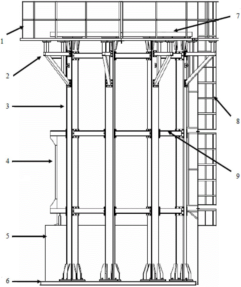
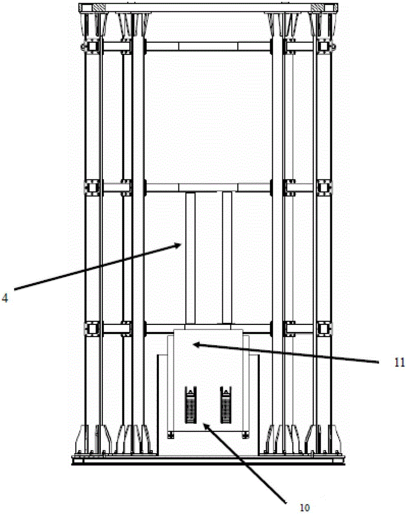
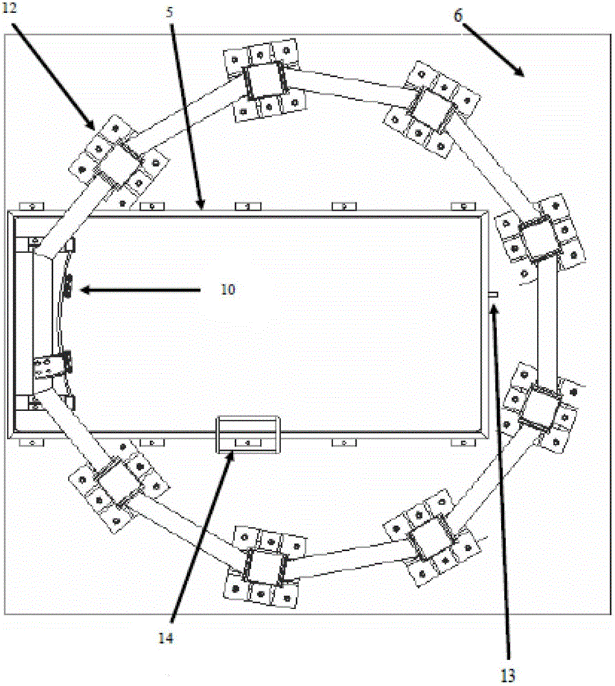
[0031] The present invention includes a personnel operation platform 1, an oblique support 2, a test platform support column 3, a simulated pressure vessel wall stand 4, a test platform simulated pool 5, a test platform base 6, a pressure vessel simulated flange 7, a test platform ladder 8, and a test platform. Platform crosspiece 9, sample box simulation metal storage rack and sample box simulation piece 10, pressure vessel simulation cylinder wall 11, test platform support column bottom flange 12, test platform simulation pool inlet and outlet pipes 13, and test platform simulation pool ladder 14.

[0032] The personnel operation platform 1 is mainly used for operators to stand beside the simulated flange of the pressure vessel and engage in operations related to reactor pressure vessel maintenance, training, tool debugging and verification. ...


PUM


Abstract

The invention relates to a reactor pressure vessel simulation test platform for a nuclear power plant. The reactor pressure vessel simulation test platform comprises a test platform base, a plurality of test platform support upright columns whose bottom ends are fixed to the test platform base, a pressure vessel simulation flange fixed to the top ends of the test platform support upright columns, a personnel operation platform fixed to the test platform support upright columns through an oblique support, a test platform crosspiece which is fixed among the test platform support upright columns and has an upper layer, a middle layer and a lower layer, a test platform ladder respectively fixed to the test platform base and the test platform crosspiece, a simulation pressure vessel cylinder wall vertical plate fixed to neighboring layers of the test platform crosspiece, and a test platform simulation pool fixed on the test platform base. The reactor pressure vessel simulation test platform can be installed in a proper workshop outside a reactor containment vessel in a nuclear power plant area. Before a set is shut down and the maintenance work begins, debugging, verifying of special-purpose tools and personnel training work can be finished.

Description

technical field [0001] The invention relates to a reactor pressure vessel simulation test platform for nuclear power plants, in particular to a reactor maintenance and training platform for nuclear power plants, the design and development of reactor irradiation supervision sample boxes, the design and development of various types of special tools for reactors, and other fields. Reactor pressure vessel simulation test platform for nuclear power plants. Background technique [0002] At present, the design and development of special tools for overhaul and maintenance of most nuclear power plant reactors in the world are basically based on the parameters provided by the design drawings of the reactor to complete the manufacture of special tools related to the reactor. For example: reactor pressure vessel inner surface and welding seam in-service inspection equipment, reactor main bolt hole automatic cleaning machine, reactor pressure vessel main bolt hole CCTV television inspect...

Claims


Application Information

Patent Timeline
Patent Type & Authority Applications(China)
IPC IPC(8): G09B25/02
Inventor 黄潜张建军张福海刘永生孙永平吴磊武仲斌
Owner JIANGSU NUCLEAR POWER CORP
Why Eureka
Try Eureka