
Back passivation layer structure, back passivation P type solar cell, preparation method of back passivation layer structure and preparation method of back passivation P type solar cell

A solar cell and back passivation technology, which is applied in the field of solar cells, can solve the problems of high transformation cost, high cost, and large space occupation, and achieve the effects of low price, small equipment footprint, and simple preparation

Inactive Publication Date: 2014-08-27
SPIC XIAN SOLAR POWER CO LTD
View PDF5 Cites 2 Cited by
  • Summary
  • Abstract
  • Description
  • Claims
  • Application Information

AI Technical Summary

Problems solved by technology

However, when the traditional production line is undergoing the transformation of the back passivation battery production line, it generally faces the problem that there is no space in the original plant to accommodate the new process equipment, and the transformation cost is too high.
Especially the SiN film layer in the traditional back passivation layer structure requires PECVD vacuum coating equipment, and PECVD vacuum coating equipment takes up a lot of space and is very expensive

Method used


Image

  • Back passivation layer structure, back passivation P type solar cell, preparation method of back passivation layer structure and preparation method of back passivation P type solar cell
  • Back passivation layer structure, back passivation P type solar cell, preparation method of back passivation layer structure and preparation method of back passivation P type solar cell
  • Back passivation layer structure, back passivation P type solar cell, preparation method of back passivation layer structure and preparation method of back passivation P type solar cell

Examples


Embodiment Construction

[0045] The rear passivation layer structure, the rear passivation P-type solar cell and the preparation method thereof proposed by the present invention will be further described in detail below with reference to the accompanying drawings and specific examples. Advantages and features of the present invention will be apparent from the following description and claims. It should be noted that all the drawings are in very simplified form and use imprecise ratios, which are only used for the purpose of conveniently and clearly assisting in describing the embodiments of the present invention.

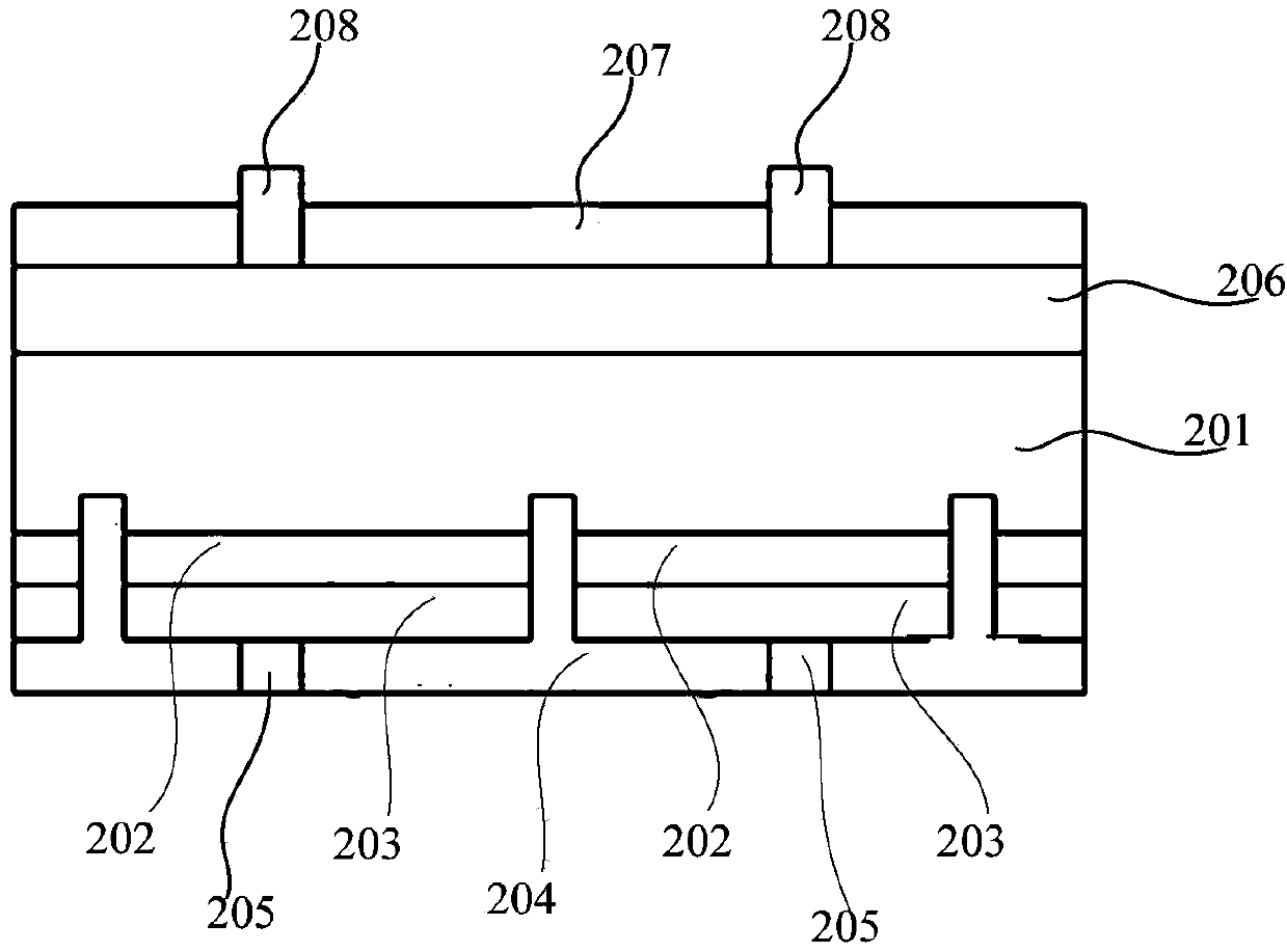
[0046] see figure 1 , figure 1 A schematic structural view of the back passivation layer structure provided for an embodiment of the present invention, such as figure 1 As shown, the back passivation layer structure provided by the present invention comprises:

[0047] al 2 o 3 A thin film 102 deposited on the back side of the P-type silicon wafer 101;

[0048] TiO 2 film 103, covere...


PUM

PropertyMeasurementUnit
Thicknessaaaaaaaaaa
Thicknessaaaaaaaaaa

Abstract

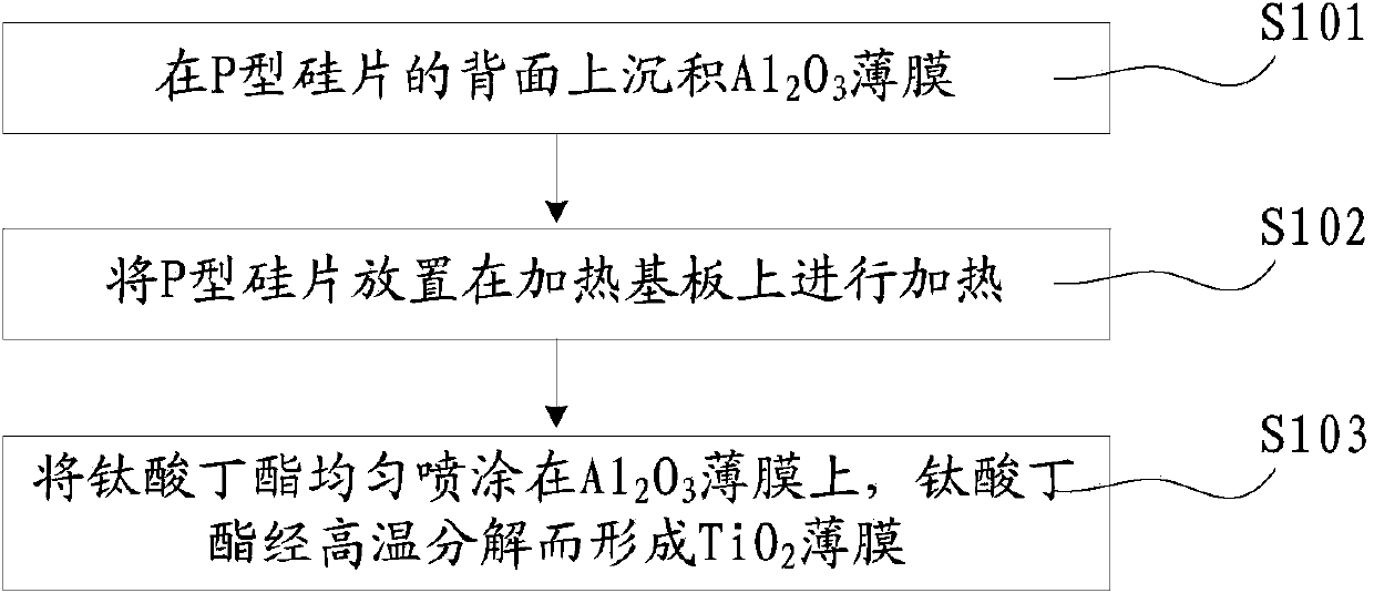
The invention discloses a back passivation layer structure and a preparation method of the back passivation layer structure. A laminated film structure of an Al2O3 thin film and a TiO2 thin film serves as the back passivation layer structure. The TiO2 thin film can be manufactured by conducting pyrolysis on butyl titanate according to a spray method, wherein specifically, a silicon wafer is placed on a heating substrate, the butyl titanate is evenly sprayed on the upper face of the silicon wafer, and the butyl titanate forms the TiO2 thin film through butyl titanate; thus, the back passivation layer structure is quite easy to prepare, and no complex preparation devices are needed. Compared with a PECVD vacuum coating device for preparing a SiN thin film, the space occupied by the device is small, and the device is simple in structure and low in price; thus, possibility is provided for refitting a back passivation cell through a normal production line. Meanwhile, the invention further discloses a back passivation P type solar cell and a preparation method of the back passivation P type solar cell. According to the cell, the laminated film structure of the Al2O3 thin film and the TiO2 thin film serves as the back passivation layer structure.

Description

technical field [0001] The invention relates to the technical field of solar cells, in particular to a rear passivation layer structure, a rear passivation P-type solar cell and a preparation method thereof. Background technique [0002] A solar cell is a semiconductor device that converts solar energy into electrical energy through the photovoltaic effect. As a new energy material, it has attracted more and more attention. [0003] Improving photoelectric conversion efficiency and reducing production costs are two main aspects of solar cell research today. There are many factors that affect the photoelectric conversion efficiency of solar cells, but these factors can be attributed to the utilization rate of solar photons and surface recombination. [0004] Improving the utilization rate of sunlight can be achieved by reducing the reflection of light: when the light hits the front surface of the battery, part of the light is reflected on the surface of the silicon wafer, an...

Claims


Application Information

Patent Timeline
IPC IPC(8): H01L31/0236H01L31/18
CPCY02E10/50H01L31/02168H01L31/068H01L31/1868Y02E10/547Y02P70/50
Inventor 陈璐吴翔董鹏高鹏宋志成郭永刚屈小勇王举亮
Owner SPIC XIAN SOLAR POWER CO LTD
Learn More