Supporting system used for rotor of high-speed and high-power interior permanent magnet synchronous motor and provided with reinforcing ribs

A permanent magnet synchronous motor and rotor support technology, which is applied to the rotating parts of the magnetic circuit, the shape/style/structure of the magnetic circuit, etc., can solve the problems that the electromagnetic performance and mechanical strength of the permanent magnet synchronous motor cannot be balanced, and achieve the improvement of electromagnetic performance , Improve the electromagnetic performance, the effect of margin increase

Inactive Publication Date: 2014-08-27
CHONGQING UNIV
View PDF4 Cites 1 Cited by
  • Summary
  • Abstract
  • Description
  • Claims
  • Application Information

AI Technical Summary

Problems solved by technology

[0005] The purpose of the present invention is to solve the problem that the electromagnetic performance and mechanical strength of the permanent magnet synchronous motor cannot be balanced

Method used


Image

  • Supporting system used for rotor of high-speed and high-power interior permanent magnet synchronous motor and provided with reinforcing ribs
  • Supporting system used for rotor of high-speed and high-power interior permanent magnet synchronous motor and provided with reinforcing ribs
  • Supporting system used for rotor of high-speed and high-power interior permanent magnet synchronous motor and provided with reinforcing ribs

Examples


Embodiment 1

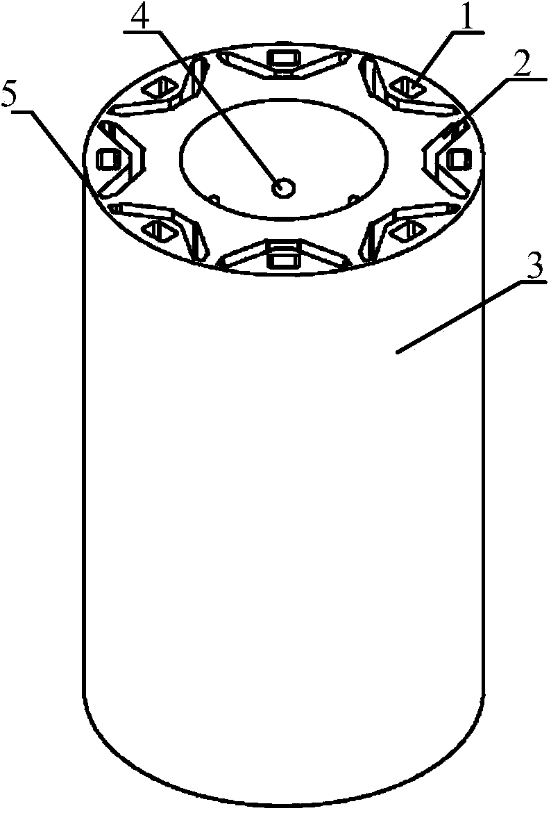
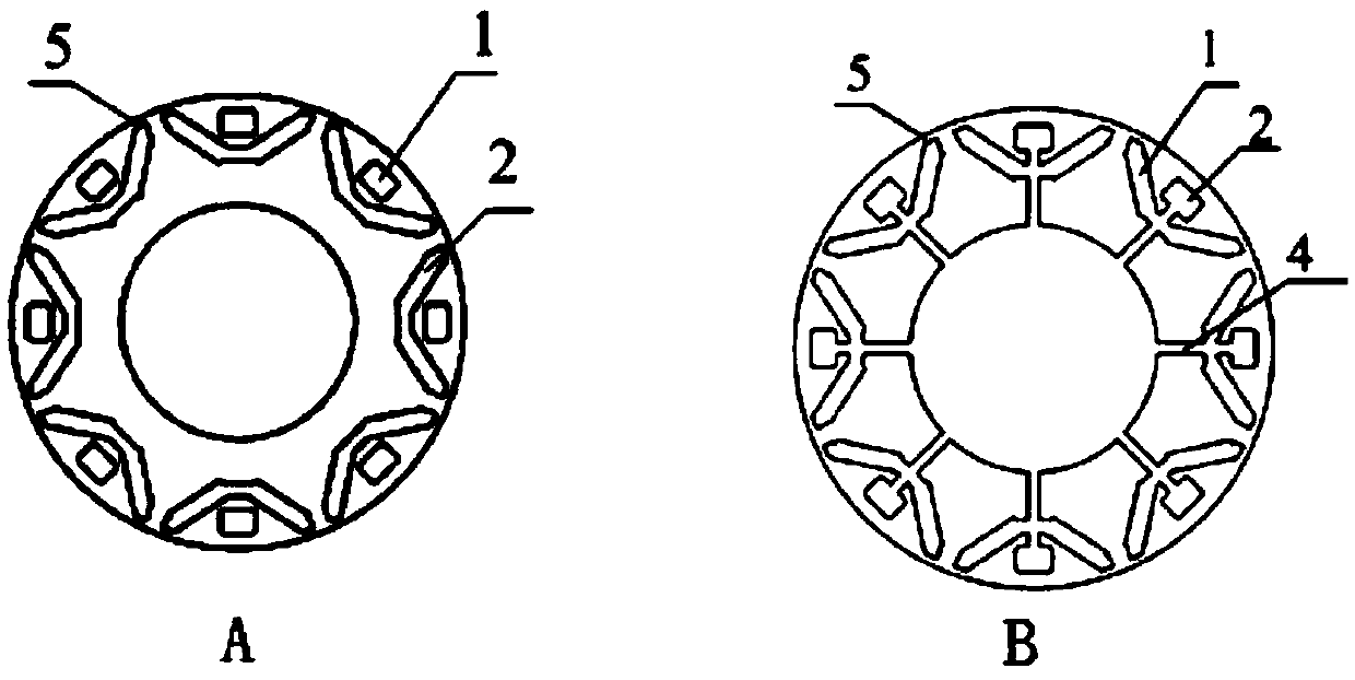
[0045] see figure 1 and Figure 6 , a high-speed and high-power built-in permanent magnet synchronous motor rotor support system with ribs. Like the existing motor rotor, the motor rotor includes a rotor core 3 , permanent magnet bars and a rotating shaft 8 , and the rotor core 3 is provided with a central axis hole and several permanent magnet slots 2 in the axial direction. In the embodiment, the cross-section of the permanent magnet slots 2 is "V" shaped, evenly distributed around the central axis hole. The part between the permanent magnet slot 2 and the outer wall of the rotor core 3 is called a magnetic isolation bridge.

[0046] Also includes screw rod 7, axle sleeve 11 and beam 6.

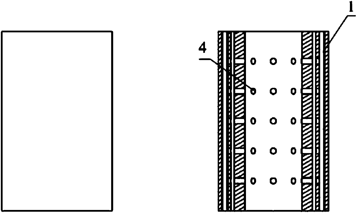
[0047] The rotor core 3 has several beam slots 1 for inserting beams 6 and several screw holes 4 for screw rods 7 to pass through.

[0048] Several beam slots 1 are distributed outside the permanent magnet slots 2 . The screw hole 4 runs through the central axis hole, the permanent mag...

Embodiment 2

[0055] see figure 1 and Figure 9, a high-speed and high-power built-in permanent magnet synchronous motor rotor support system with reinforcing ribs, including a rotor core 3, a permanent magnet bar and a rotating shaft 8, the rotor core 3 has a central axis hole and several Permanent magnet slots 2, the permanent magnet slots are distributed around the central hole. In the embodiment, the cross-section of the permanent magnet slots 2 is "V" shaped, evenly distributed around the central axis hole. The part between the permanent magnet slot 2 and the outer wall of the rotor core 3 is called a magnetic isolation bridge.

[0056] It also includes screw rod 7, beam 6 and dovetail tenon 12.

[0057] The rotor core 3 has several beam slots 1 for inserting beams 6 and several screw holes 4 for screw rods 7 to pass through.

[0058] Several beam slots 1 are distributed outside the permanent magnet slots 2 . The screw hole 4 runs through the central axis hole, the permanent magne...

Embodiment 3

[0067] The main structure of this embodiment is the same as that of Embodiment 1 or 2, and the rotor core 3 is formed by laminating several silicon steel sheets I and several silicon steel sheets II.

[0068] The center of the silicon steel sheet I has a central shaft hole through which the rotating shaft 8 passes. Around the shaft hole of the silicon steel sheet I, there are distributed some permanent magnet slots 2 for the permanent magnet bars to pass through. The outer side of the permanent magnet slot 2 has a beam slot 1 through which the beam 6 passes.

[0069] The center of the silicon steel sheet II has a central shaft hole through which the rotating shaft 8 passes. Around the shaft hole of the silicon steel sheet II, there are several permanent magnet slots 2 for the permanent magnet bars to pass through. The outer side of the permanent magnet slot 2 has a beam slot 1 through which the beam 6 passes. The silicon steel sheet II also has screw grooves. One end of th...


PUM


Abstract

The invention discloses a supporting system used for a rotor of a high-speed and high-power interior permanent magnet synchronous motor and provided with reinforcing ribs. The supporting system aims to solve the problem that high electromagnetic performance and high mechanical strength of the permanent magnet synchronous motor can not be achieved at the same time. The supporting system comprises a rotor core, permanent magnet bars and a rotating shaft. A center shaft hole and a plurality of permanent magnet grooves are formed in the rotor core in the axial direction, and the permanent magnet grooves are distributed around the center shaft hole. The supporting system further comprises screws, a shaft sleeve and cross beams. The rotor iron is provided with a plurality of beam grooves and a plurality of screw holes. The shaft sleeve is a hollow cylinder, and the side wall of the cylinder is provided with a plurality of through holes for the screws to penetrate out. The cross beams are provided with threaded holes for one ends of the screws to be screwed in. After the shaft sleeve is inserted into the center shaft hole and the cross beams are inserted into the cross beam grooves, one ends of the screws penetrate through the through holes first, then penetrate through the screw holes and are screwed into the threaded holes in the cross beams at last.

Description

technical field [0001] The invention relates to the technical field of motor design and manufacture, in particular to a rotor support system suitable for high-speed and high-power built-in permanent magnet synchronous motors. Background technique [0002] Permanent magnet synchronous motors have many significant advantages such as simple structure, high operational reliability, high power density, and flexible shapes and sizes of motors. In line with the needs of economic development for energy saving and emission reduction, it can not only partially replace traditional electric excitation motors, but also achieve high efficiency that electric excitation motors cannot achieve. It is used in centrifugal compressors, aerospace, high-speed electric spindles, new energy power generation and distributed High-speed direct drive fields such as power supply systems have broad application prospects. [0003] While the permanent magnet synchronous motor has superior performance, it a...

Claims


Application Information

Patent Timeline
Patent Type & Authority Applications(China)
IPC IPC(8): H02K1/28H02K1/27
Inventor 黄嵩李浩廖勇刘刃胡光伟房姗姗
Owner CHONGQING UNIV
Why Eureka
Try Eureka