Vertical annular welding tool

A girth welder, vertical technique

Active Publication Date: 2014-09-10
GREAT WALL MOTOR CO LTD
View PDF6 Cites 15 Cited by
  • Summary
  • Abstract
  • Description
  • Claims
  • Application Information

AI Technical Summary

Problems solved by technology

[0003] ①Repetitive ring welding rotation leads to different degrees of fatigue of supporting elements such as shielding gas, compressed air, and circuit control, leakage of compressed air and shielding gas delivery pipelines, breakage or leakage of control lines in circuit control, etc. Fault;
[0004] ②There are many circuit controls, which leads to confusion of the whole welding control system and poor maintainability;
[0005] ③Welding angle and speed adjustability are relatively poor, and welding quality stability is poor
[0008] (1) The welding torch angle cannot meet the requirements
Interference between the welding torch and the workpiece or the cooperation between the column and the welding torch cannot reach the position of the weld;
[0009] (2) The welding stability of the arc will be unstable
When the welding base material (workpiece) is a large-diameter material, the fixing mechanism of the welding torch will become very long, and there will be a situation of reluctance when reaching the weld position, and the stability of the weld quality cannot be guaranteed;
[0010] (3) When the workpiece has special circumstances such as large top and bottom small or irregular (irregular bulges on the outer edge or other special circumstances that will cause the upper workpiece to be larger than the outer edge of the lower workpiece on the plane), the patent cannot complete the welding or cannot guarantee Stability of welding quality

Method used


Image

  • Vertical annular welding tool
  • Vertical annular welding tool
  • Vertical annular welding tool

Examples


Embodiment

[0048] Example Vertical girth welding tooling

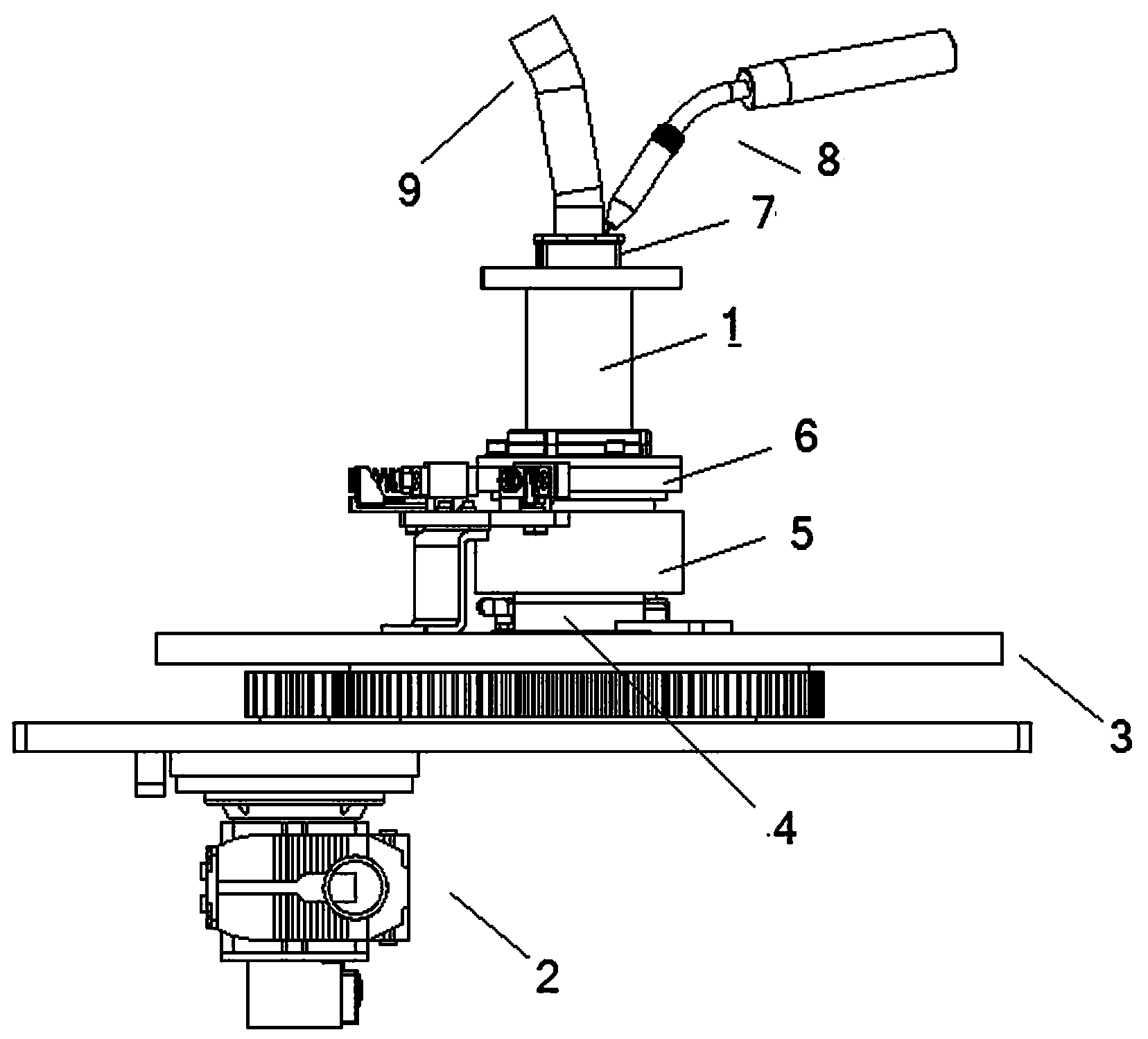
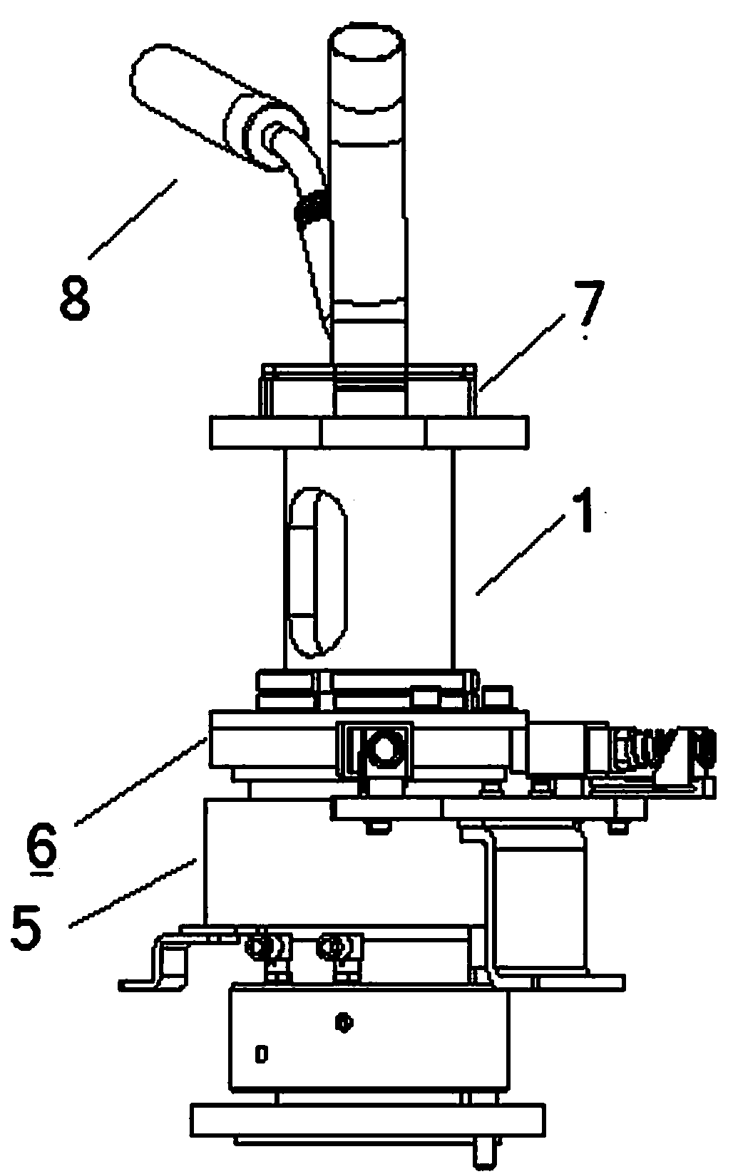
[0049] reference figure 1 , figure 2 , Figure 5 , Image 6 , This embodiment includes a fixed horizontally extending base, and also includes a rotatable platform 3 and a hollow column 1.

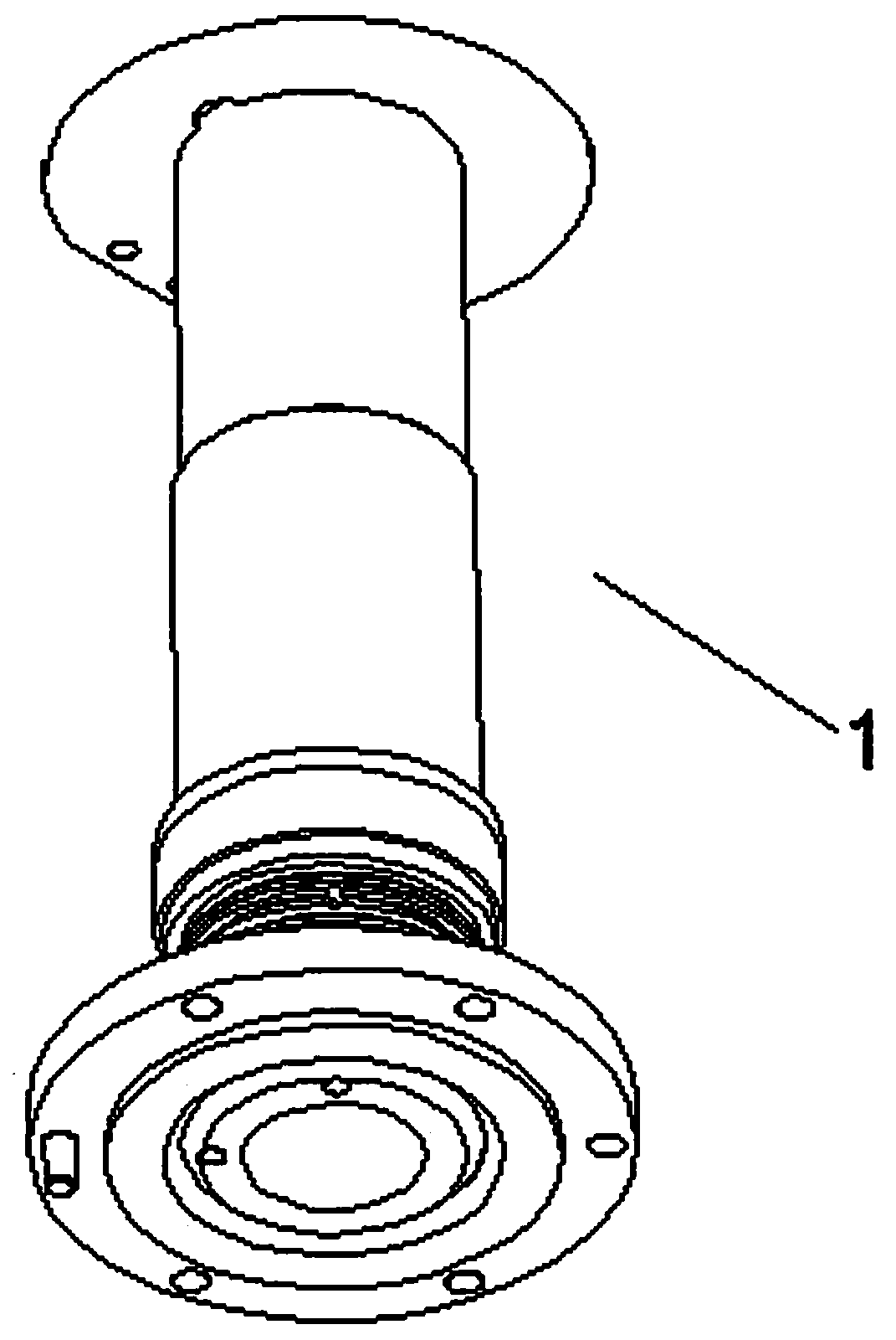
[0050] The overall structure of column 1 is as image 3 versus Figure 4 Shown. The column 1 is fixed on the base and extends upward. The column 1 is covered with an air guide ring 4, a conductive ring 5, and a grounding copper ring 6 from bottom to top. A workpiece positioning mechanism 7 is fixed on the upper part of the column 1 by bolts.

[0051] The hollow cavity of the column 1 is provided with an air circuit connected with the air guide ring 4 and an electric control circuit connected with the conductive ring 5, and a welding ground wire connected with the grounding copper ring 6 is also provided.

[0052] The speed reduction mechanism 2 is fixed on the base, the output end is a vertical rotating shaft, and the vertical rotating shaft is c...


PUM


Abstract

The invention discloses a vertical annular welding tool. The vertical annular welding tool comprises a rotatable platform and a hollow upright column, wherein the hollow upright column is perpendicular to the rotatable platform and sleeves the rotatable platform via a clearance; a gas guiding ring, a conductive ring and a ground wire grounding copper ring sleeve the upright column; a gas circuit, an electric control circuit and a welding ground wire are arranged in a hollow cavity of the upright column; a workpiece positioning mechanism is fixed on the upper portion of the upright column; and a wire feeding machine and a welding gun mechanism are fixed on the rotatable platform. Rotating power is provided by using a speed reducer; circuit transmission is carried out by using the conductive ring; and gas is turned on, turned off and changed over via the gas guiding ring, the welding gun can be adjusted multi-dimensionally in space, namely, the welding gun can be adjusted in the up-down direction and the left-right direction at an angle, annular welding between tubes, annular welding between a tube and a flange and annular welding between a tube and a plane can be performed, the product differentiation switching efficiency and the welding quality are improved, the welding angle and the welding speed can be freely adjusted, annular welding can be performed rotatably without limitation, workpieces do not need to rotate, and the time can be greatly saved. The vertical annular welding tool is suitable for annular welding between the tubes, annular welding between the tube and the flange and annular welding between the tube and the plane, or is suitable for welding an arc.

Description

technical field [0001] The invention belongs to the field of mechanical processing, and relates to welding equipment for metal components, in particular to a vertical ring welding tool. Background technique [0002] In the prior art, the traditional girth welding technology used in pipe-to-flange welding and pipe-to-pipe welding generally has the following defects: [0003] ①Repetitive ring welding rotation leads to different degrees of fatigue of supporting elements such as shielding gas, compressed air, and circuit control, leakage of compressed air and shielding gas delivery pipelines, breakage or leakage of control lines in circuit control, etc. Fault; [0004] ②There are many circuit controls, which leads to confusion of the whole welding control system and poor maintainability; [0005] ③Welding angle and speed adjustability are relatively poor, and the stability of welding quality is poor. [0006] A round welding device disclosed in the Chinese patent literature d...

Claims


Application Information

Patent Timeline
Patent Type & Authority Applications(China)
IPC IPC(8): B23K9/32B23K9/02
CPCB23K9/0286B23K9/0288B23K9/287B23K9/323B23K37/0461
Inventor 郭宏王海东
Owner GREAT WALL MOTOR CO LTD
Why Eureka
Try Eureka