A large field of view staring spectral imaging system and imaging method thereof

A spectral imaging and imaging system technology, applied in high-resolution spectral imaging system and its imaging field, can solve the problems of high spectral resolution, low spectral resolution, instantaneous field of view limitation, etc., and achieve high spectral resolution and simple structure Compact, inherently low aberration effect

Inactive Publication Date: 2017-03-29
SUZHOU UNIV
View PDF4 Cites 4 Cited by
  • Summary
  • Abstract
  • Description
  • Claims
  • Application Information

AI Technical Summary

Problems solved by technology

Traditional spectral imaging systems using planar and concave diffraction gratings are limited by aberrations, resulting in low spectral resolution; such systems based on convex gratings can obtain strong aberration balance capabilities by adopting a reasonable optical structure, and then obtain good results. The spatial image and high spectral resolution, but it has an incident slit and the instantaneous field of view is limited. It is necessary to use push-broom imaging to achieve a large imaging field of view. The acquired spectral image has temporal inconsistency and cannot Accurately reflect the real situation in the full field of view at the same time
Therefore, it is difficult to obtain a spectral imaging system with uniform dispersion, high spectral resolution and large field of view at the same time using traditional or existing optical imaging systems

Method used


Image

  • A large field of view staring spectral imaging system and imaging method thereof
  • A large field of view staring spectral imaging system and imaging method thereof
  • A large field of view staring spectral imaging system and imaging method thereof

Examples


Embodiment 1

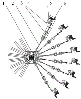
[0026] This embodiment provides a staring spectral imaging system with a large field of view, high resolution, and multi-layer sub-aperture structure. It works in the visible light band of 0.48µm to 0.65µm. For F / #=2.2.

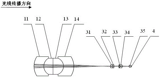
[0027] See attached figure 1 , which is a schematic diagram of the optical system structure of the large field of view staring spectral imaging system provided in this embodiment; the front objective lens with multi-layer sub-aperture mainly consists of a concentric spherically symmetrical lens 1 and 64 compensating mirror units 3 to form a compensating mirror array, The concentric spherically symmetrical lens adopts a fully glued design, and a unit of the compensating mirror array 3 is composed of two groups of double glued and a single lens. Lens 12, spherical positive lens 13, spherical negative lens 14, curved surface intermediate image 2, spherical negative lens 31 of compensation lens group, spherical positive lens 32, spherical positive lens 33, spher...

Embodiment 2

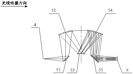
[0035] In this embodiment, the working wavelength range is 0.48µm~0.65µm, the full field of view is 100º, and the F number of the spectroscopic imaging system is F / #=2.2. For the optical system structure of the imaging system, please refer to the attached figure 1 ; For the optical path diagram of the front objective lens and the spectroscopic imaging system, please refer to the attached figure 2 And attached image 3 .

[0036] The remaining parameters of the optical imaging system are as follows: the focal lengths of the single-aperture system of the front objective lens and the spectroscopic imaging system are 40mm and 110mm respectively, along the light direction, the spherical negative lens of the front objective lens is 11, the spherical positive lens is 12, the spherical positive lens is 13, and the spherical negative lens 14. The radii of curvature of the spherical negative lens 31, the spherical positive lens 32, the spherical positive lens 33, the spherical negativ...


PUM


Abstract

The invention relates to a large field of view staring type spectral imaging system and an imaging method thereof. Its front objective lens and spectroscopic imaging system respectively adopt the optical structure of refraction and reflection / diffraction hybrid; After the multi-aperture field of view and further fine correction of aberrations, the obtained multi-field, high-performance, and full-band aerial image is used as the target of the subsequent spectroscopic imaging system. After dispersion and focusing imaging by the spectroscopic imaging system, each The aperture channel obtains the spectral image in the corresponding field of view, and after fusion and stitching, the spectral image of the entire field of view is obtained. The invention solves the problem of time inconsistency caused by using the traditional push-broom method to acquire spectral images, has the advantages of large field of view, compact structure, good spectral image quality, strong light collection ability, and high spectral resolution, and is suitable for aviation and aerospace Hyperspectral remote sensing imaging.

Description

technical field [0001] The invention relates to a staring spectral imaging system and its imaging method for quickly acquiring high-performance spectral images in a large field of view, in particular to a multi-layer sub-aperture structure combining refraction and reflection / diffraction High-resolution spectral imaging system and its imaging method. Background technique [0002] Spectral imaging technology can obtain the third-dimensional spectral information while obtaining the two-dimensional space image of the target object, which can explore the essence of things more deeply and comprehensively. One of the important means, it can be used to complete various tasks, such as remote sensing imaging, object classification and recognition, target detection, industrial production process monitoring and control, food safety and testing, medical diagnosis, land resource investigation, environment and disaster monitoring, etc. It is a major difficulty for this type of imaging sys...

Claims


Application Information

Patent Timeline
Patent Type & Authority Patents(China)
IPC IPC(8): G01J3/28
Inventor 季轶群高艳红
Owner SUZHOU UNIV
Why Eureka
Try Eureka