Vacuum leak detection method and vacuum leak detection system for containers

A leak detection and vacuum technology, which is applied in the direction of using liquid/vacuum degree for liquid tightness measurement, and by measuring the acceleration and deceleration rate of fluid, etc., can solve problems such as misjudgment, achieve high detection accuracy, avoid false detection, and mechanism structure simple effect

Inactive Publication Date: 2014-09-10
TRUKING TECH LTD
View PDF8 Cites 28 Cited by
  • Summary
  • Abstract
  • Description
  • Claims
  • Application Information

AI Technical Summary

Problems solved by technology

This is because in the case of a large leak in the plastic ampoule, when the airtight chamber is evacuated, a negative pressure environment will be formed quickly in the plastic ampoule, and the vacuum degree in the plastic ampoule is the same as that in the airtight chamber. After the time Tc, the vacuum degree in the airtight chamber will still remain within the allowable range, resulting in misjudgment

Method used


Image

  • Vacuum leak detection method and vacuum leak detection system for containers
  • Vacuum leak detection method and vacuum leak detection system for containers
  • Vacuum leak detection method and vacuum leak detection system for containers

Examples


Embodiment 1

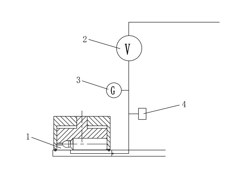
[0041] Such as Figure 5 As shown, the vacuum leak detection system of this embodiment includes an air pump 2, an airtight chamber 1 for accommodating the object to be inspected (plastic ampoule 10), and an air suction channel 9 connecting the air pump 2 and the airtight chamber 1. The channel 9 is connected with a detection device for detecting the degree of vacuum, and a quantitative control component for controlling the pumping volume is also provided on the pumping channel 9 , and the quantitative control component adopts a flow meter 5 . When working, the air pump 2 pumps air to the airtight chamber 1, and the amount of air pumping is controlled by the flow meter 5; the detection device detects the degree of vacuum in the airtight chamber 1.

[0042] In this embodiment, the detection device is a vacuum pressure gauge 3 and a pressure sensor 4, wherein the pressure sensor 4 can detect the degree of vacuum in the airtight chamber 1, and feed back the signal to the control mec...

Embodiment 2

[0047] Such as Image 6 As shown, the vacuum leak detection system of this embodiment is basically the same as that of Embodiment 1. The difference is that this embodiment is also provided with a control valve 11 on the air extraction channel 9, and the control valve 11 can control the flow of the air extraction channel 9. Off, it can use a solenoid valve. When the control valve 11 is connected to the air extraction channel 9, the airtight chamber 1 can be evacuated, and when the control valve 11 is disconnected from the air extraction channel 9, the airtight chamber 1 after the air extraction can be kept under pressure. , and then control the control valve 11 to communicate with the air extraction channel 9 to perform exhaust.

Embodiment 3

[0049] Such as Figure 7 As shown, this embodiment is basically the same as Embodiment 2, the difference is that the vacuum leak detection system of this embodiment is provided with four airtight chambers 1, and each airtight chamber 1 is connected to an air extraction channel 9, all The air extraction channel 9 is connected with the air pump 2 through a main channel 13, that is, the main channel 13 communicates with the inlet port (air inlet) of the air pump 2, and one end of each air extraction channel 9 communicates with the airtight chamber 1, and the other end communicates with the airtight chamber 1. The main channel 13 communicates. A vacuum pressure gauge 3, a pressure sensor 4 and a control valve 11 are provided on each air extraction channel 9, and the air extraction pump 2 simultaneously evacuates the four airtight chambers 1 during use. On each pumping channel 9 , the vacuum pressure gauge 3 and the pressure sensor 4 detect the vacuum degree of the corresponding a...


PUM


Abstract

The invention discloses a vacuum leak detection method and a vacuum leak detection system for containers. The vacuum leak detection method comprises the steps of placing a container to be detected in an airtight chamber, quantitatively pumping the airtight chamber, detecting the vacuum degree in the airtight chamber and judging whether the container leaks after a preset period of time, and the like. The vacuum leak detection system comprises an air pump, an airtight chamber used for accommodating an object to be detected, and a pumping channel connecting the air pump and the airtight chamber. A detection device used for detecting the vacuum degree is connected to the pumping channel. The vacuum leak detection system further comprises a quantitative control assembly used for control. The vacuum leak detection method and the vacuum leak detection system of the invention have the advantages of accurate and reliable detection, high detection precision, and the like.

Description

technical field [0001] The invention relates to the technical field of vacuum leak detection, in particular to a vacuum leak detection method and a vacuum leak detection system for a container. Background technique [0002] In the field of pharmaceutical machinery, the production process of the plastic ampoule blow-fill-seal integrated machine linkage line mainly includes extrusion bottle making, filling and sealing, residual material removal and leak detection. After the ampoule card is sent to the filling and sealing station to complete the filling and sealing, it is then sent to the die-cutting station to remove the remaining material of the bottle card (the twisting groove can also be cut at the die-cutting station at the same time), and the remaining bottle is removed The card is then sent to the leak detection station for leak detection, so as to reject the unqualified products with leakage, and finally get the finished bottle card with multiple ampoules (the single am...

Claims


Application Information

Patent Timeline
Patent Type & Authority Applications(China)
IPC IPC(8): G01M3/32
Inventor 王业洲
Owner TRUKING TECH LTD
Why Eureka
Try Eureka