Blood Component Separator

A technology of separator and hollow body, applied in blood filtration, biochemical equipment, suction equipment, etc., can solve the problems of difficulty in extracting high-purity stem cells and inconvenient operation, and achieve the effects of reducing treatment costs, preventing pollution, and preventing infection

A technology of separator and hollow body, applied in blood filtration, biochemical equipment, suction equipment, etc., can solve the problems of difficulty in extracting high-purity stem cells and inconvenient operation, and achieve the effects of reducing treatment costs, preventing pollution, and preventing infection

CN104039372BActive Publication Date: 2016-02-10TS CELLMEDI CO LTD

Image

  • Blood Component Separator
  • Blood Component Separator
  • Blood Component Separator

Examples


Embodiment Construction

[0071] Hereinafter, embodiments of the present invention will be described in detail with reference to the accompanying drawings. Reference is made to the drawings wherein like reference characters designate like or corresponding parts throughout the views. In the embodiments of the present invention, detailed descriptions of well-known properties and structures that are judged to make the gist of the present invention unnecessarily obscure are omitted.

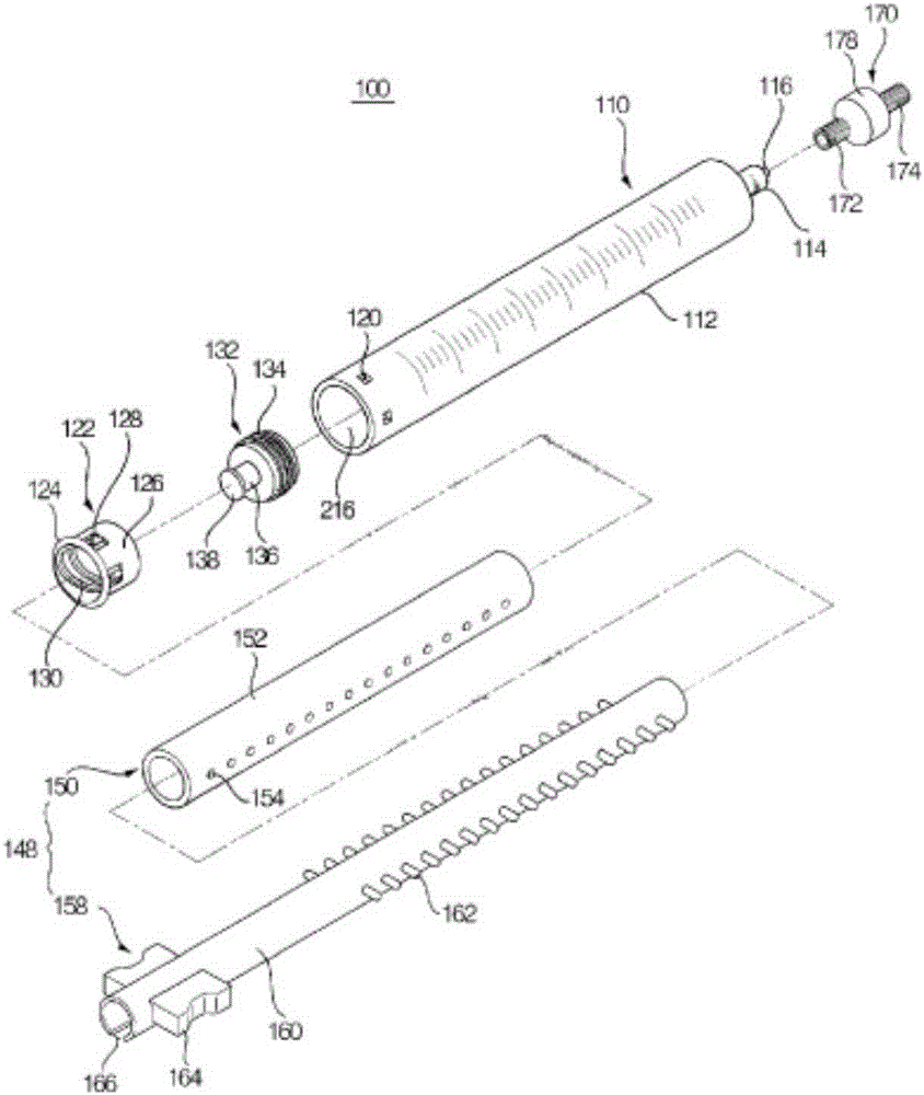
[0072] The blood component separator 100 of the present invention basically includes a hollow body 110 , a piston 132 , and the piston 132 is movably installed in the hollow body 110 .

[0073] The hollow body 110 includes a flow tube 116 formed at one end of the hollow body 110 . Body fluids are injected into the hollow body 110 or extracted from the hollow body 110 through the flow tube 116 . The internal threaded part 122 acts as a stopper, and the stopper is coupled with the other end of the hollow body 110 .

[0074] ...


PUM


Abstract

The present invention discloses a blood component separator, which can ensure the purity of, for example, separated blood components or stem cells, and can prevent contamination by outside air during the process of separating components, and at the same time, compared with the prior art, Simplifies the separation process. The component separator includes: a hollow main body including a flow tube formed at one end for guiding fluid and a stopper provided at the other end; and a piston mounted on the main body to move back and forth to vary the spacing between the flow tube and the top of the piston; wherein the piston has a collection formed at the top, and the rearward movement of the piston is limited by the stopper.

Description

technical field [0001] The present invention relates to a blood component separator, and more particularly to a blood component separator capable of ensuring, for example, the purity of separated blood components or stem cells and preventing contamination of ambient air during the separation of components, the separator's The operation process is more simplified compared with related prior art. Background technique [0002] Blood is roughly divided into blood cells and plasma. Blood cells include red blood cells, white blood cells, and platelets, and plasma mainly includes the liquid part of blood that contains coagulation factors and electrolytes, etc., which are essential to sustain life. [0003] Separation of blood components is required for various medical purposes. For this reason, various methods of extracting blood components by separating blood are widely used. Among them, a centrifugation process of centrifuging blood components with different specific gravity a...

Claims


Application Information

Patent Timeline
10 Feb 2016
Publication
CN104039372B
IPC
A61M1/02; A61M1/34; C12M1/24
CPC
A61M1/02; C12M47/04; A61M1/3693; A61M1/029; B01L3/5021; A61M2202/0437; B01L3/5635; B01L2200/026
Inventors
金俊佑