Revolution machine as well as deceleration method and deceleration device thereof

A technology of reduction gear and rotary machine, which is applied in the direction of measuring devices, mechanical equipment, and mechanical parts testing, etc., and can solve problems such as electrical reduction gear and motor damage, unstable noise, and damage to the deceleration circuit.

Active Publication Date: 2014-09-17
ZHENGZHOU RES INST FOR ABRASIVES & GRINDING CO LTD
View PDF9 Cites 5 Cited by
  • Summary
  • Abstract
  • Description
  • Claims
  • Application Information

AI Technical Summary

Problems solved by technology

[0004] However, the above two deceleration devices have obvious shortcomings during use and can only intervene when the main shaft naturally decelerates to a low-speed section (the deceleration stage includes a high-speed section with a high initial speed and a low-speed section with a low speed in the later stage). , so that the duration of the deceleration phase cannot be significantly shortened. The reason is that when the mechanical deceleration device intervenes in the high-speed section to decelerate, the mechanical deceleration device will generate a large reverse impact load on the main shaft, so that the nut that fixes the grinding wheel on the main shaft Loosening and falling off will cause damage to the grinding wheel and rotary machine; when the electric reducer adopts a DC excitation device to decelerate, it can only intervene when the motor frequency is less than 5HZ. If the motor frequency is greater tha

Method used


Image

  • Revolution machine as well as deceleration method and deceleration device thereof
  • Revolution machine as well as deceleration method and deceleration device thereof
  • Revolution machine as well as deceleration method and deceleration device thereof

Examples


Embodiment Construction

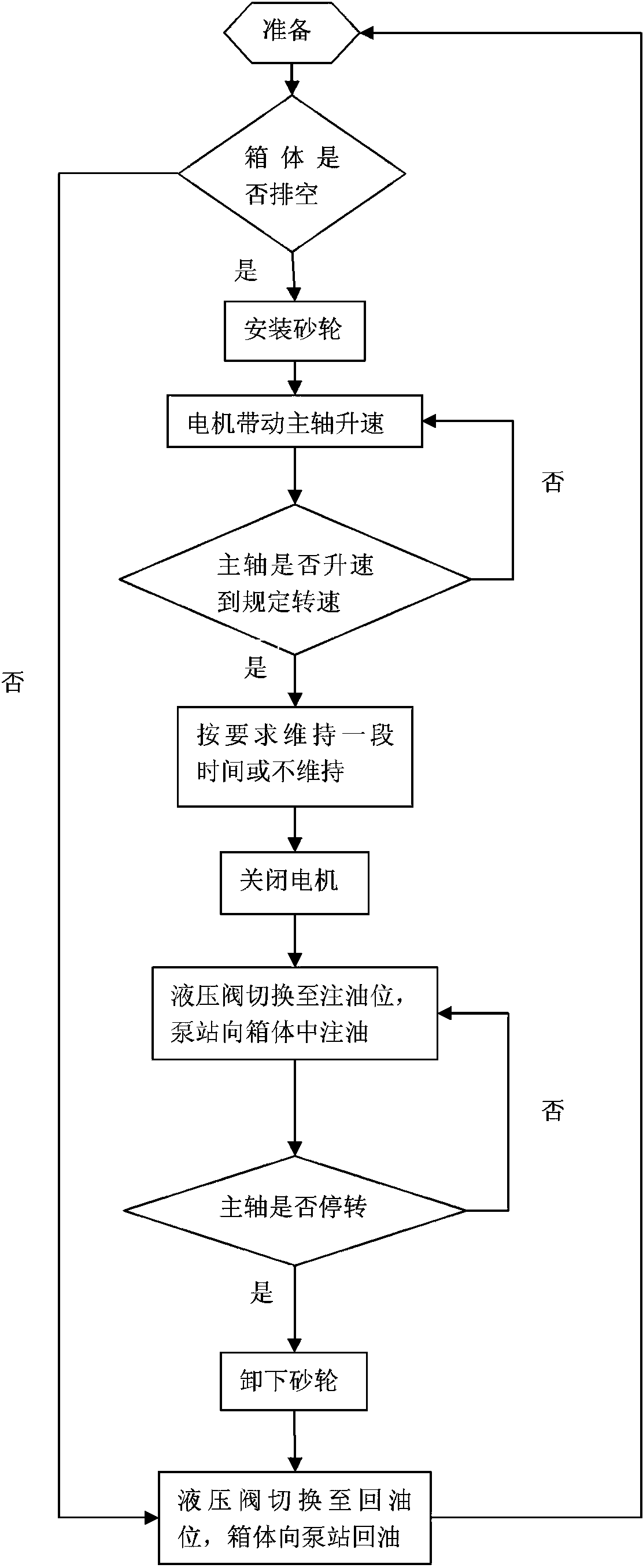
[0023] Embodiment of the deceleration method of rotary machine in the present invention: this deceleration scheme comprises the following steps:

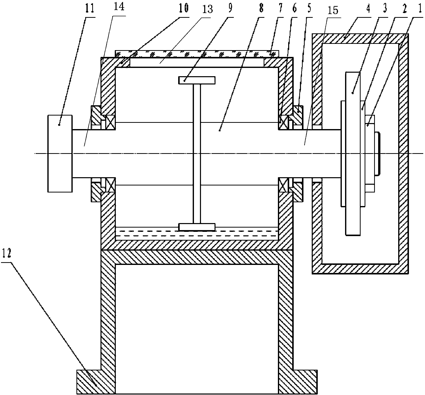
[0024] Step 1. Set the reduction shaft integrally connected with the main shaft of the rotary machine. The reduction shaft is located in the middle of the main shaft and rotates with the main shaft. The main shaft of the rotary machine includes a power input section and a grinding wheel installation section integrally connected at both ends of the reduction shaft. The power input section and the grinding wheel The installation section passes through the opposite sides of the container, and the deceleration shaft is relatively rotatable assembled on the container through the power input section and the grinding wheel installation section. The deceleration shaft is fixed with agitating paddles hanging on its outer periphery, and the agitation paddles In the container, there is a gap between the overhanging end of the stirring blade and...


PUM


Abstract

The invention discloses a revolution machine as well as a deceleration method and a deceleration device thereof. A main shaft of the revolution machine is fixedly or integrally connected with a deceleration shaft; the deceleration shaft is fixedly provided with a stirring paddle which is suspended at the periphery of the deceleration shaft and is positioned in a container; the container is provided with an opening through which a deceleration liquid can be gradually injected during a deceleration stage of the main shaft; during initial stage of deceleration, since a liquid level is relatively low, the deceleration liquid generates less resistance to the stirring paddle, the main shaft does not decelerate abruptly under driving of the deceleration shaft; along with rising of liquid level of the deceleration liquid, the deceleration liquid stirring depth of the stirring paddle is also gradually increased, i.e., the length, inserted into the deceleration liquid, of the suspended end of the stirring paddle is also gradually increased, so that the resistance to the deceleration shaft is also synchronously increased; the rotation speed of the main shaft driven by the deceleration shaft is slowly reduced, but the resistance generated to the deceleration shaft by the deceleration liquid is gradually increased, thereby ensuring that a nut used for fixing a grinding wheel on the fixed main shaft does not loosen, and ensuring the safety of the grinding wheel and the revolution machine.

Description

technical field [0001] The invention relates to a rotary machine used for the test of the rotational strength of the grinding wheel, and also relates to a deceleration method of the rotary machine and a deceleration device specially used for implementing the deceleration method. Background technique [0002] The rotational strength of the grinding wheel refers to the ability of the grinding wheel to resist cracking under the action of centrifugal force during the rotation of the grinding wheel, which reflects the tensile stress of the grinding wheel. It is the most important quality index related to equipment and personal safety in the manufacture and use of the grinding wheel. Generally, in the factory inspection of the grinding wheel, the rotary strength test must be carried out through the rotary machine. When performing the rotary strength test, the grinding wheel is first fixed on the main shaft of the rotary machine, and then the main shaft is raised to the specified sp...

Claims


Application Information

Patent Timeline
IPC IPC(8): F16D57/02G01M13/00G01N3/02
Inventor 吕申峰陈学伟张良包华
Owner ZHENGZHOU RES INST FOR ABRASIVES & GRINDING CO LTD
Why Eureka
Try Eureka