
Method for measuring sub-surface affected layer depth and morphology of optical material

A technology of sub-surface damage and optical materials, applied in the direction of electric/magnetic depth measurement, electric/magnetic thickness measurement, measuring device, etc., can solve the problems of complex data processing, complicated sample preparation process, unintuitive test results, etc., and achieve test results High precision, strong applicability, suitable for large-scale promotion

Active Publication Date: 2014-09-24
XIAN TECHNOLOGICAL UNIV
View PDF4 Cites 17 Cited by
  • Summary
  • Abstract
  • Description
  • Claims
  • Application Information

AI Technical Summary

Problems solved by technology

[0006] The present invention provides to overcome the problems of complicated sample preparation process, unintuitive test results and complicated follow-up data processing existing in the prior art

Method used


Image

  • Method for measuring sub-surface affected layer depth and morphology of optical material
  • Method for measuring sub-surface affected layer depth and morphology of optical material
  • Method for measuring sub-surface affected layer depth and morphology of optical material

Examples


Embodiment Construction

[0028] The present invention will be further described in detail below in conjunction with the accompanying drawings and specific embodiments.

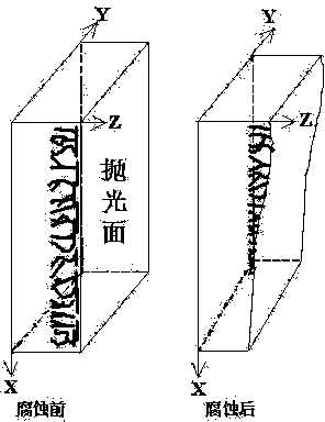
[0029] The sub-surface damage layer of the optical element includes a sub-surface crack layer and an internal stress deformation layer, and is covered by a polishing relamination layer on the non-damage substrate. Because it is below the surface, it is not easy to observe directly.

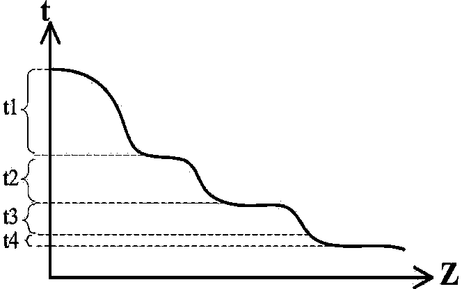
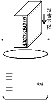
[0030] The invention provides a method for measuring the depth and shape of the subsurface damage layer of an optical material. The method controls the sample to move continuously and slowly along the vertical direction in the HF acid solution, and uses HF acid to continuously corrode the sample. , so that the corrosion degree of different positions and layers of the sample changes continuously, and the corroded section surface is obtained. The corroded cut surface is scanned with a probe-type profiler, and the depth of the subsurface damage layer of the...


PUM


Abstract

The invention relates to the technical field of optical precise measurement, especially a method for measuring the sub-surface affected layer depth and morphology of an optical material. The method comprises the steps: firstly enabling a sample to be clamped on a clamping mechanism in uniform motion; controlling the clamping mechanism to enable the HF acid solution to immerse in the sample till the sample is completely merged in the solution; quickly extracting the sample from the solution, and employing a probe-type contourgraph to measure a corroded profile, thereby obtaining the profile curves in the longitudinal depth direction of a crack and the vertical movement direction of the sample; calculating the height difference between a critical point or a pole point and a starting point or the height difference between the critical point projected on an original surface or a pole point on the original surface and a starting point on the original surface through the critical point or the pole point and the starting point recorded in a measurement process, wherein the critical point or the pole point are the points where data obtained on the curves starts to level off, and the height difference is the sub-surface affected layer depth D of the sample; and employing an optical microscope to observe the three-dimensional shape of a corroded plane. The method provided by the invention is simple, quick and accurate, can measure the sub-surface affected layer depth and the three-dimensional shape, is high in testing precision, is low in cost, is high in visualization, and exerts low requirements on testing equipment.

Description

technical field [0001] The invention relates to the technical field of optical precision measurement, in particular to a method for detecting the depth and shape of a subsurface damaged layer of a continuously corroded optical material, which is used for measuring various optical elements ranging from planes to spherical surfaces and aspheric surfaces. This method can amplify the subsurface damage of optical materials, and can obtain the continuously changing subsurface crack depth curves on the subsurface polishing layer, damage layer and substrate, and can realize the measurement of the depth of the tiny subsurface damage layer caused by ultra-precision grinding. Background technique [0002] Quantitatively determining the depth and distribution of subsurface damage in optical materials plays an extremely important role in studying the damage formation mechanism and optimizing processing parameters. Furthermore, controlling the depth of the damaged layer and improving th...

Claims


Application Information

Patent Timeline
IPC IPC(8): G01B7/26G01B7/06G01B11/24
Inventor 田爱玲王春慧田玉珺王红军朱学亮刘丙才
Owner XIAN TECHNOLOGICAL UNIV
Learn More