Hydraulic transmission and control system for press machine

A technology of hydraulic transmission and control system, which is applied in the directions of fluid pressure actuation system components, fluid pressure actuation devices, mechanical equipment, etc., and can solve the problems of poor reliability, high oil temperature and noise, and high maintenance costs.

Active Publication Date: 2014-10-01
沈阳中大机械有限公司
View PDF2 Cites 9 Cited by
  • Summary
  • Abstract
  • Description
  • Claims
  • Application Information

AI Technical Summary

Problems solved by technology

[0003] Purpose of the invention: The present invention provides a hydraulic transmission and control system for presses, the purpose of ...

Method used


Image

  • Hydraulic transmission and control system for press machine
  • Hydraulic transmission and control system for press machine
  • Hydraulic transmission and control system for press machine

Examples


specific Embodiment approach

[0027] Detailed ways: The present invention will be further described below in conjunction with accompanying drawing:

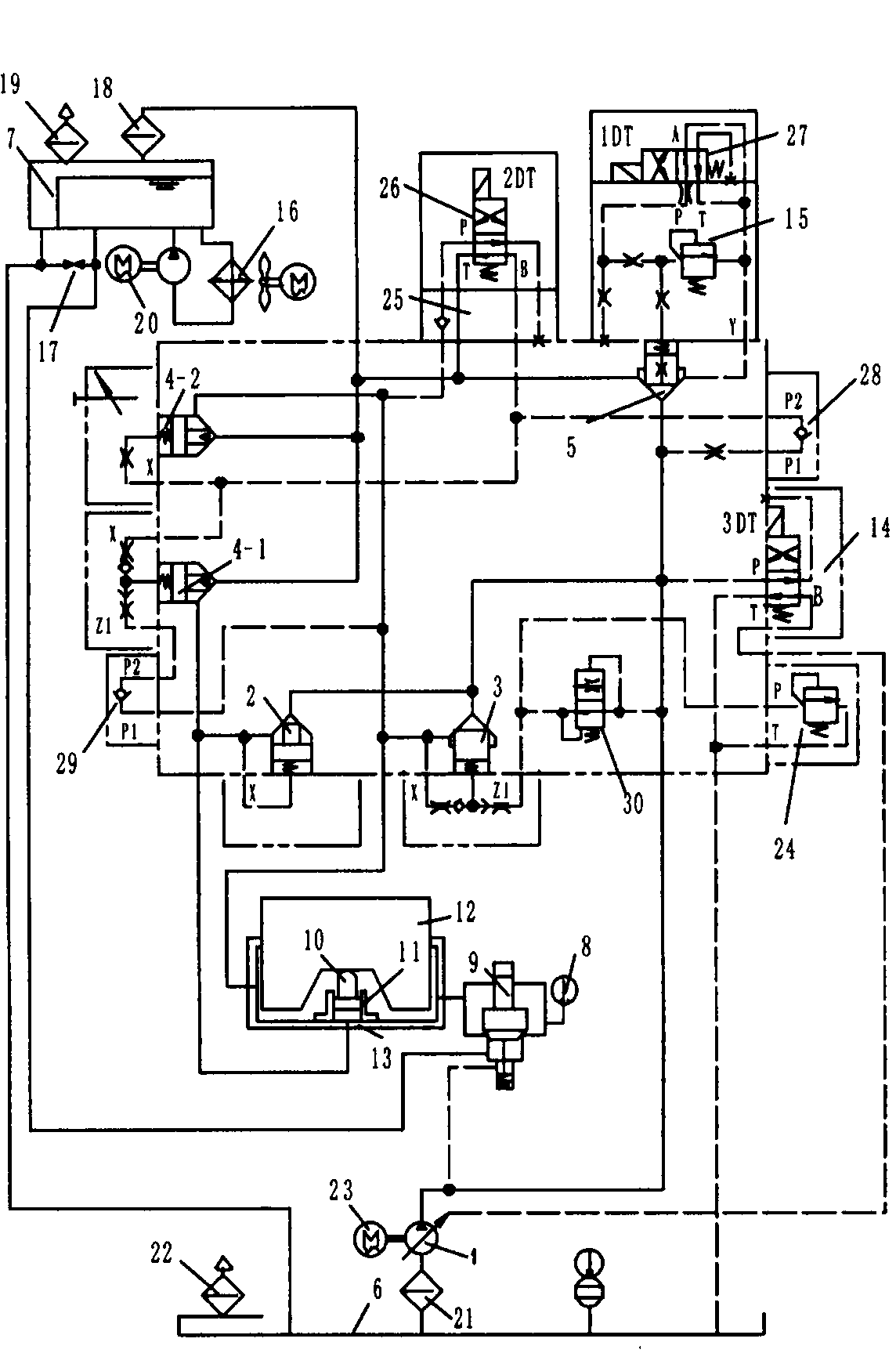
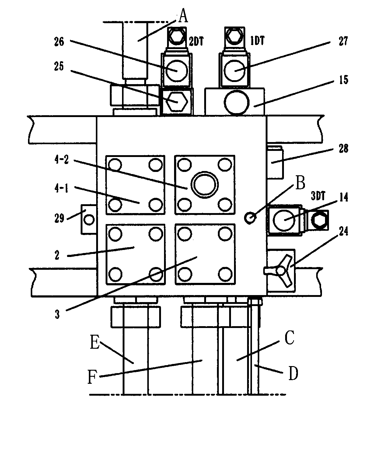
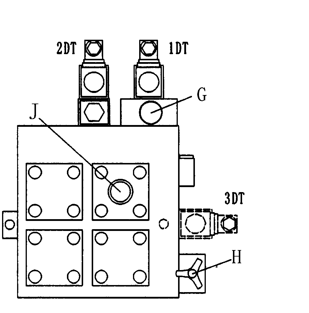
[0028] The present invention provides a hydraulic transmission and control system for a press, the system includes a combined valve block under centralized control and a small hydraulic cylinder 11 connected thereto, a large hydraulic cylinder 13, a main oil tank 6 and an auxiliary oil tank 7; A first cartridge valve 2, a second cartridge valve 3, a third cartridge valve 4-1, a fourth cartridge valve 4-2, a fifth cartridge valve 5, and a flow limiting valve 30 are installed on the combined valve block. , electromagnetic reversing valve 14, pilot relief valve 24, first electromagnetic reversing valve 27, second electromagnetic reversing valve 26 and one-way valve 28; the combined valve block of centralized control is provided with a connecting channel; the main oil tank 6 is connected The hydraulic pump 1 supplies oil to the hydraulic pump 1; the hydraulic p...


PUM


Abstract

The invention provides a hydraulic transmission and control system for a press machine. The system is characterized by comprising a centralized-control combined valve block, as well as a small hydraulic cylinder, a large hydraulic cylinder, a main oil tank and a sub oil tank which are connected with the centralized-control combined valve block. The system thoroughly changes the traditional hydraulic transmission and control system for a press machine; the original pressure applying/pressure maintaining valve block and sequence control valve are combined into a uniform 'combined valve block'; the traditional slide valve control is changed into advanced cartridge valve control; the original speed regulation-free/throttling speed regulation feeding is changed into volume speed regulation; according to the system provided by the invention, an oil temperature is regulated in an air-cooling manner for replacing water-cooling regulation.

Description

technical field [0001] The invention provides a hydraulic transmission and control system, which belongs to the field of fluid transmission and control. The application field is pressure machinery, and is especially suitable for ironing and embossing machines in the leather industry. Background technique [0002] The original press control system of the same kind is slide valve type or discrete valve block type, scattered in different positions, so not only the wiring is messy, the operation and maintenance are cumbersome, but also the pressure loss is large and there are potential safety hazards. In addition, the original form of speed regulation without work or throttling speed regulation, sometimes does not meet the process requirements. In addition, the original method has high oil temperature, high noise, poor reliability and high maintenance cost. Contents of the invention [0003] Purpose of the invention: The present invention provides a hydraulic transmission and...

Claims


Application Information

Patent Timeline
IPC IPC(8): F15B11/16F15B13/06F15B21/04C14B1/56C14B1/54
Inventor 宋俊
Owner 沈阳中大机械有限公司
Why Eureka
Try Eureka