
Low-speed wind tunnel fluorescent silk thread based on fiber threads and flow visualization method thereof

A flow display and fiber line technology, applied in aerodynamic tests, machine/structural component testing, measuring devices, etc., can solve the health hazards of highly destructive respiratory mucosal researchers, without considering the radiation of phosphor powder, and without consideration Suitable for high wind speed and other problems, to achieve good display effect, reasonable size and small impact

Inactive Publication Date: 2014-10-01
LOW SPEED AERODYNAMIC INST OF CHINESE AERODYNAMIC RES & DEV CENT
View PDF5 Cites 19 Cited by
  • Summary
  • Abstract
  • Description
  • Claims
  • Application Information

AI Technical Summary

Problems solved by technology

Wool that can glow under the irradiation of purple light has a relatively large diameter and is not suitable for high wind speeds. Wool with a small diameter cannot meet the test requirements because it does not emit light and the tail is easy to scatter during the blowing process.
Some domestic wind tunnels have adopted the method of stirring and drying the wool with a smaller diameter and phosphor solution, and then using a purple light to stimulate light emission. This method can also be applied to flow display tests, but it does not consider the radiation of phosphor powder and its impact on The high destructiveness of the respiratory mucosa is harmful to the health of scientific researchers

Method used


Image

  • Low-speed wind tunnel fluorescent silk thread based on fiber threads and flow visualization method thereof

Examples


Embodiment Construction

[0026] All the features disclosed in this specification, or all disclosed methods or steps in the process, except for mutually exclusive features and / or steps, can be combined in any manner.

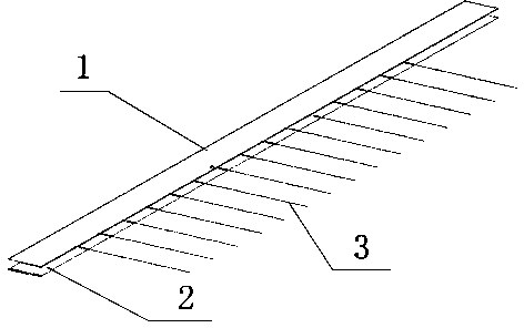
[0027] The implementation of the present invention is mainly embodied in the selection of threads. The distance between the fiber threads is determined according to the surface flow field of the test model. Generally, the fixed thread distance is 25mm and the thread length is 25mm. This size is based on long-term flow display test experience, and the wire diameter is 0.08mm. In the case of a wind speed of 70m / s, the front edge of the upper surface of the aircraft wing in the low-speed wind tunnel is between 0.17mm and 0.19mm. In the fluorescent silk flow display test technology, the silk reflects the model boundary layer Flow, the thread should be less than the thickness of the surface layer. The wool yarns used in the past are all 1mm in diameter, and its thickness is much greater than the...


PUM


Abstract

The invention discloses a low-speed wind tunnel fluorescent silk thread based on fiber threads and a flow visualization method thereof. The fluorescent silk thread comprises paper tape, adhesive tape and a plurality of fluorescent silk thread bodies. One side of the paper tape is a sticking surface, and the surface of the sticking surface is smooth; the sticky side of the adhesive tape and the sticking surface of the paper tape are stuck together; the fluorescent silk thread bodies are stuck between the paper tape and the adhesive tape. A light source of a specific wave length is adopted to induce the fluorescent silk thread bodies to emit light, and then the silk thread in the test condition is shot through photographic equipment. The method has the advantages of being easy to operate, capable of being applicable to low wind speed tests and the like. The specially-made fiber threads are odorless, nontoxic, environmentally friendly, good in display effect, low in price and good in softness and less influence surface flow fields of test models.

Description

Technical field [0001] The invention relates to the field of low-speed wind tunnel surface flow display test, in particular to a low-speed wind tunnel fluorescent thread flow display method based on fiber thread. Background technique [0002] In the low-speed wind tunnel test, the phenomenon of the flow around the model is very complicated, and theoretical methods cannot fully and accurately describe these complex flows. In recent years, the emergence of flow display technologies such as particle imaging velocimetry (PIV), shadow technology, pressure sensitive paint technology (PSP), holographic interference technology, etc., has made great progress in flow field display and measurement technology. Most display technologies are more complicated to operate in wind tunnels, and the preparatory work efficiency is not high, and the later data processing requirements are relatively high. The technology is not too mature, and some are in the research and development stage. Most low-spe...

Claims


Application Information

Patent Timeline
Patent Type & Authority Applications(China)
IPC IPC(8): G01M9/04
Inventor 张鹏周维鑫倪章松黄勇张卫国车兵辉谢琦蒋科林李士伟任章涛黄明其姜裕标孙海生
Owner LOW SPEED AERODYNAMIC INST OF CHINESE AERODYNAMIC RES & DEV CENT
Learn More